Apples vs. oranges, anybody? In this thread we’ll take a look at speaker cables from an RF perspective, not something usually discussed. Although closer to my professional life than the usual audio analysis, I would not have thought of this except for the prodding by (“interaction with” if you prefer) a fellow engineer. I would have said transmission line effects at audio frequencies are negligible. Was I wrong? Well, the jury is still out, but it makes for an interesting thread, so here we go!
Recall that wires have impedance terms (resistance, inductance, capacitance, conductance – RLCG) distributed along their length. They reduce the cable’s bandwidth, reduce the effective damping factor at the speaker terminals, and add distortion (though the cable’s nonlinearity at audio is insignificant – I am not covering that now). Also remember that it takes time to get from one end of the wire to the other, even for an ideal line. Finally, you may recall from the DAC Reflections thread that mismatches among the source (amplifier), line (speaker cable), and load (speaker) impedances cause reflections. That is, not all the energy goes straight into the load as we would hope, but some gets reflected back. The bigger the mismatch, the bigger the reflection, the less signal is initially delivered to the load, and the longer it takes to settle to its final value.
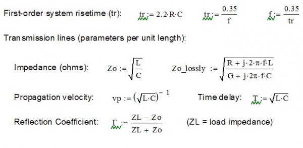
First, let’s get the equations out of the way:
Note vp is for the electrical signal, not the sound waves out of the speaker! Sound travels around 1130 feet/s, while the signal in the wires typically travels about 1/2 the speed of light (1/2 of 186 thousand miles/s) for an audio cable (can be 0.9c or more for RF cables). The good news is I am not going to use these equations any more, but they are the basis of the pictures that follow. For more info, look up transmission lines on Wikipedia or your favorite RF handbook.
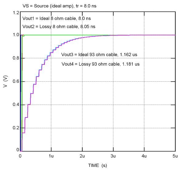
Now let’s look at a simple circuit formed by an ideal amplifier (a perfect voltage source), a short (20-foot) speaker cable, and ideal 8-ohm resistor to model the speaker. For speaker cables I used an ideal and lossy 8-ohm cable, and ideal and lossy 93-ohm cable that is essentially the original Monster Cable. The delay time is ~45 ns for these cables. I applied a step input with a 10 ns edge (8 ns rise time, equivalent to ~44 MHz bandwidth). The results for several test cases are shown in Figure 2, with the output voltages measured at the load.
Now, with an 8-ohm cable and 8-ohm load the match is perfect so no reflections occur (gamma = 0). It is difficult to see but the ideal 8-ohm cable rises smoothly in 8 ns and starting 45 ns after the input step as expected. The lossy 8-ohm cable is nearly the same, but with one tiny little perturbation at the top (barely visible in the green line) and rise time is 8.05 ns. I cannot imagine anyone would hear any impact from either 8-ohm cable.
The 93-ohm case is much more interesting. Now we see mismatches causing reflections and the resulting longer settling time. Because of the mismatch between line (93 ohms) and load (8 ohms), only part (about 16 %) of the initial energy is absorbed, and the rest is reflected (“bounced”) back to the amp. There it is again reflected (100% since the amp is ideal), and travels back to the load (speaker), adding a bit more power but again reflecting most of the energy back. We see the signal at the speaker building in steps throughout this process. This back and forth goes on for several microseconds as seen in the picture, with the voltage at the speaker gradually rising as a little more energy is passed on to the load at each “bounce”. The effective rise time is now about 1.2 us (~300 kHz bandwidth) – still well above the audible band, but much lower than the ideally-matched case. Again, the difference in rise time between the ideal 93-ohm line (1.16 us) and lossy line (1.18 us) is insignificant.
Let’s talk just a bit about this bouncing that is going on… Some of us are old enough to remember those hard rubber “Superballs”, and the rest have hopefully seen how a small plastic ball bounces. I am going to use that for an analogy (and yes, I know this is not terribly rigorous, please bear with me). The ball is the signal, and the ground the load. What we’d like is for the load (ground) to instantly absorb all of the ball’s (signal) energy, giving nothing back. This would be like throwing the ball into a pool of thick, gooey mud. One splat, and that’s it. The other extreme would be smooth concrete. The ball hits and bounces, bounces nearly as high the second time, and bounces many times before all its energy is gone. Only a little is transferred to the concrete with each contact. In between is something like grass; a few bounces and we’re done. Perfect energy transfer would be like mud, with a reflection coefficient of 0, and concrete is a coefficient of almost 1 with almost no energy transferred.
The question of whether the mismatch matters is an interesting one. I think it is safe to say that a 45 ns reflection is unlikely to be heard by anyone. Our ears should average those little steps so we don’t hear them (I think). As for the effective change in rise time, a 20 kHz sine wave has a rise time of 17.5 us, about an order of magnitude slower than the cable. So, the 93-ohm cable would have to be ten times longer (200 feet) to approach the rise time of a 20 kHz signal. Or, have an impedance ten times higher, i.e. a cable with very low capacitance and/or very high inductance. There may be such cables; I do not know. From a rise time, or bandwidth, perspective the cable does not seem to matter.
The other argument that has been made is how the reflections impact our perception of location. It was shown in a much earlier thread (not one of mine, though I did run some numbers) that we can actually perceive timing changes in the microsecond region. This is based upon our ability to recognize a small shift in location which, when calculated as a time difference between our two ears, works out to just a couple of microseconds. So, might a relative time shift of 1 – 2 us caused by reflections be noticed? The problem with this theory is that, treated as a time constant, again there is an order of magnitude between the cable’s time constant and that of a 20 kHz signal. The audio signal, especially when comprised of many different tones (like music), may well mask the effect. And, the reflections operate upon all signals, meaning all edges are delayed. Finally, if the mismatch is the same for each speaker, the same signal will have the same equivalent time delay for each speaker. Of course, different frequencies will see different impedances in real speakers, thus the reflections will be different for different frequencies. This could cause the image to shift (vary) with frequency. Clearly it can get complicated... What is also clear is that transmission line effects can matter in speaker cables, though whether these effects are audible I can’t say.
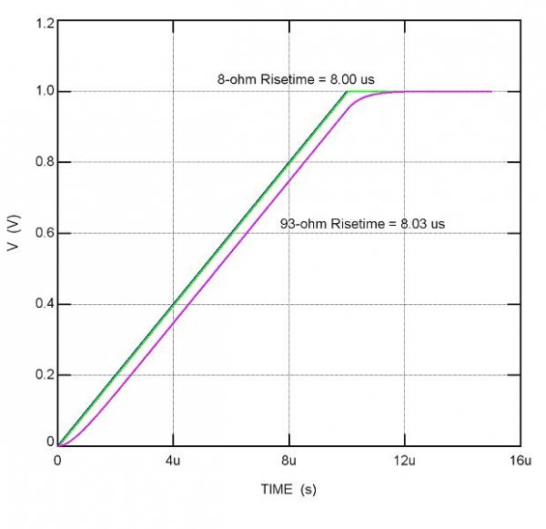
One last look at this fairly ideal case: what if a more realistic (slower) rise time is used? A 10 us edge (8 us rise time, a little over 40 kHz) is shown in Figure 3. The reflection “stair steps” are no longer visible and the rise time is essentially the same as the source (8 us) for the 8-ohm and 93-ohm traces. The delay caused by the distributed RLC of the 93-ohm line is visible, however. The 8-ohm lines’ delay is about 45 ns, as expected from T calculated above, but the 93-ohm lines’ delay is about 0.5 us. An ideally-matched line and load renders the LC essentially “invisible”, but a mismatch means the distributed impedance is “visible” and impacts the propagation delay consistent with the effective bandwidth. Again, the audibility is a matter of some debate…
The analysis for bi-wiring is also very interesting, but another day…


