Hi,
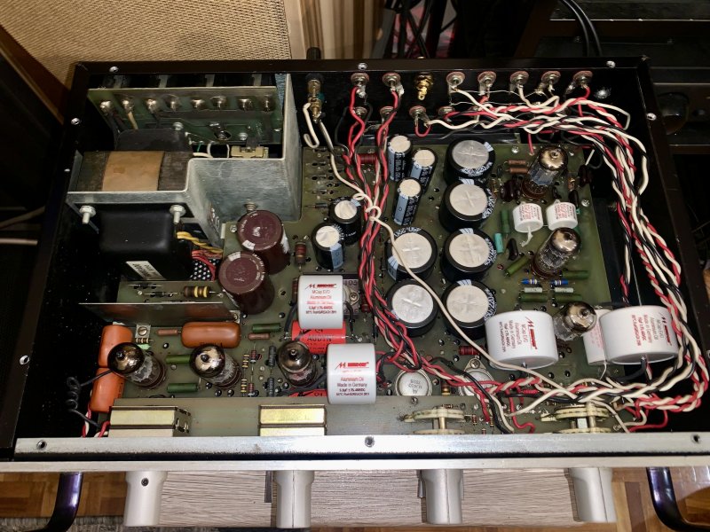
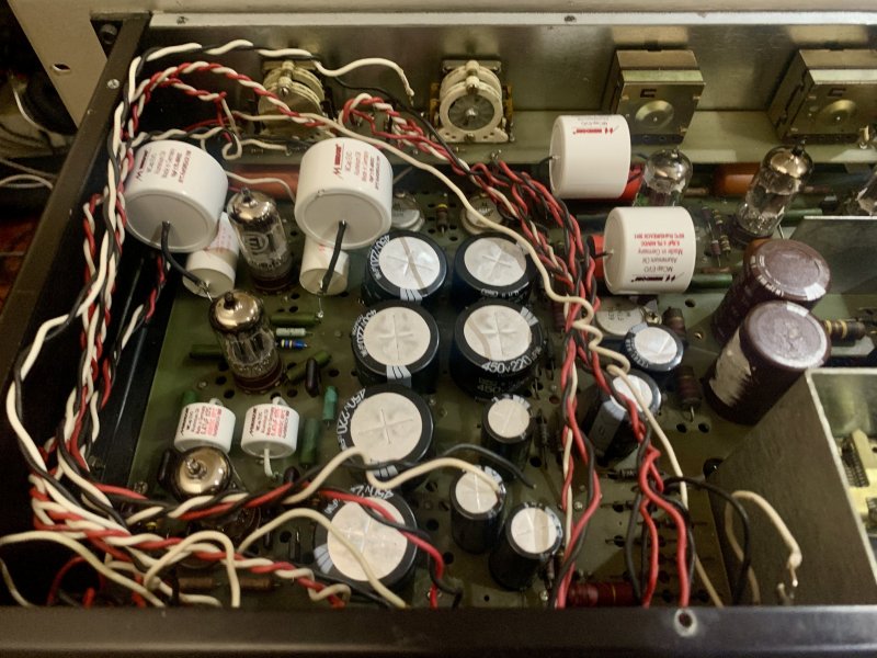
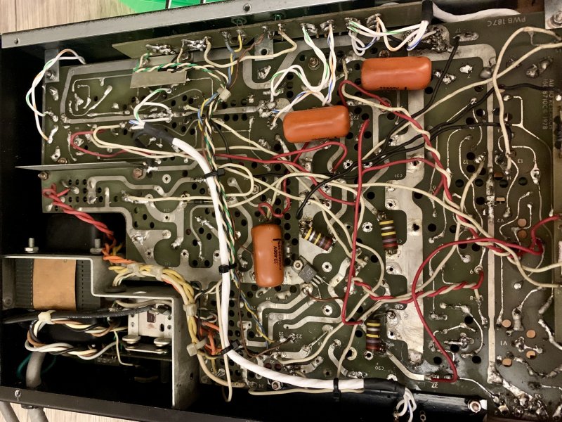
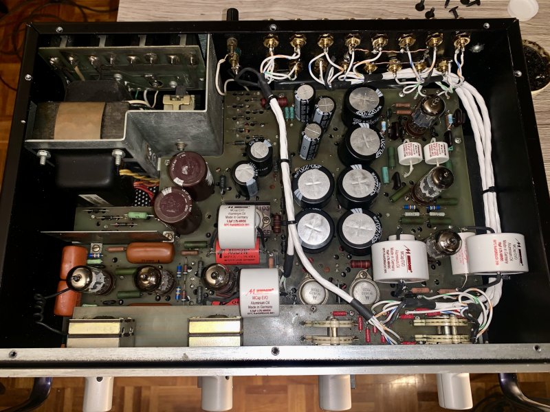
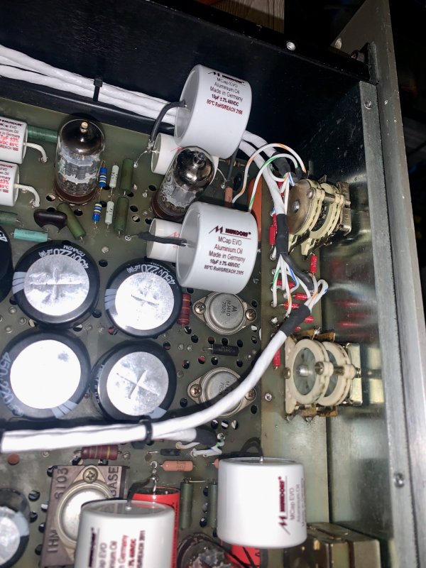
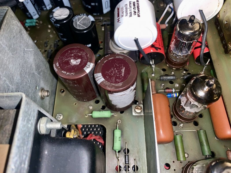
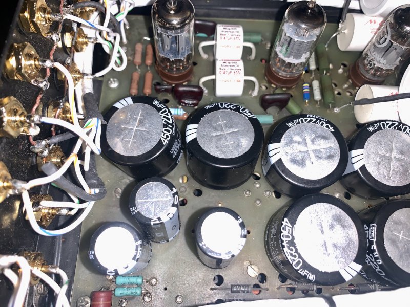
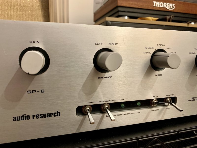
I have an SP-6A I purchased used. The previous owner says he got it from an estate sale. The unit had the electrolytics recapped about 10 yrs ago. All works well except for the MODE selector. In Stereo Reverse Mode, only the the left side outputs sound. the other thing I find odd is all the wiring was replaced with solid core twisted pair. mostly the signal wires. but also some of the power wires. The guy who did this didn't do a very good job. very messy. not twisted neatly and routed any which way. Sacrilege!. Lol..
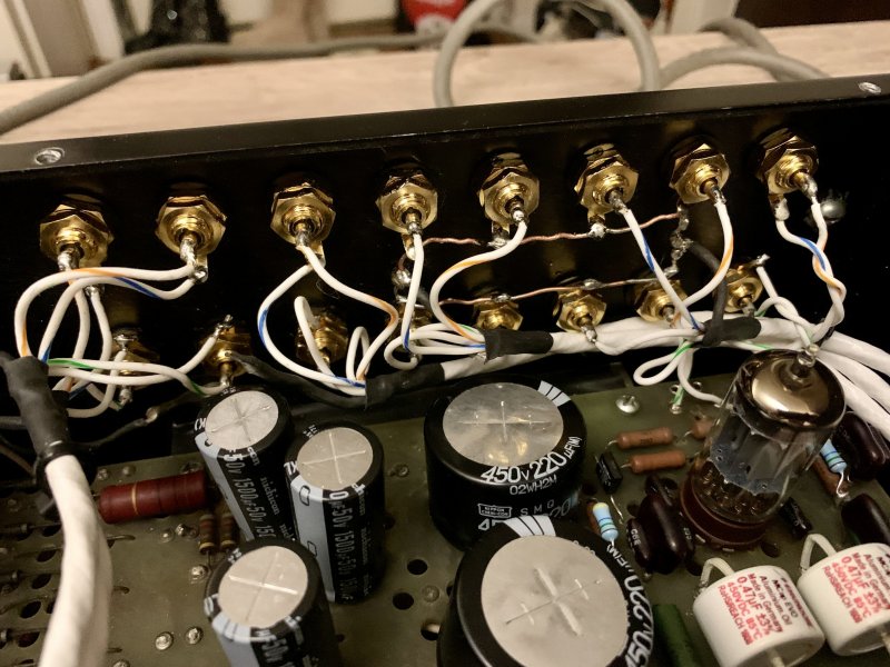
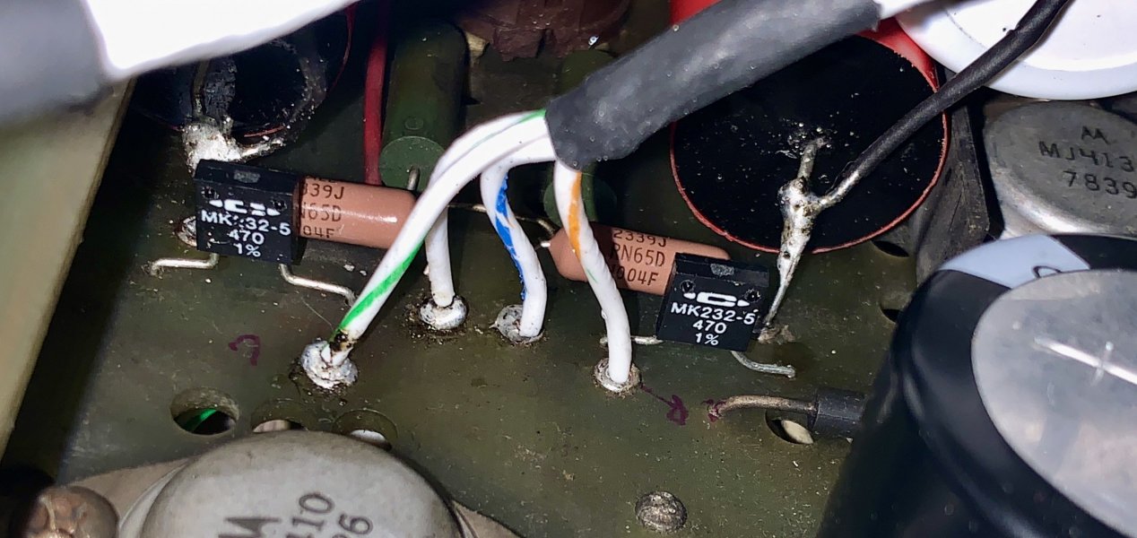
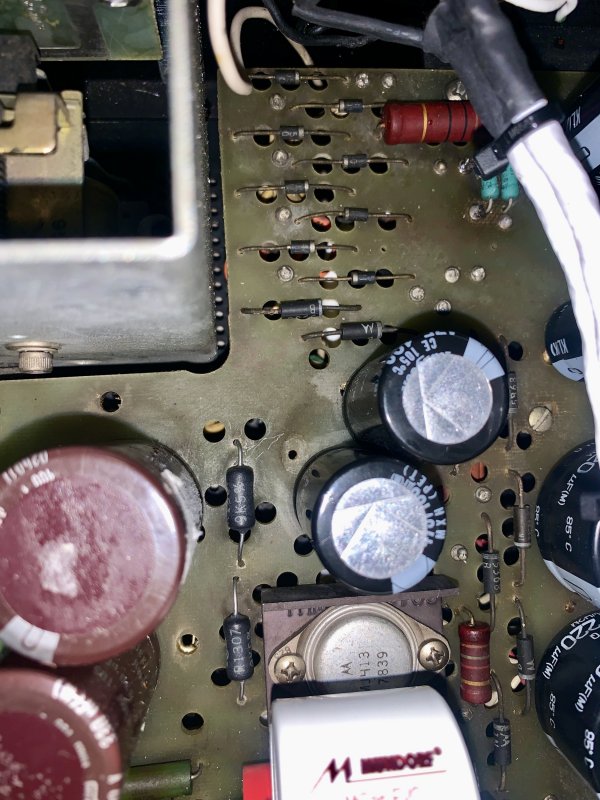
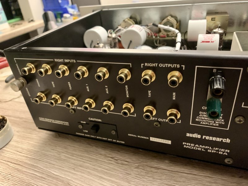
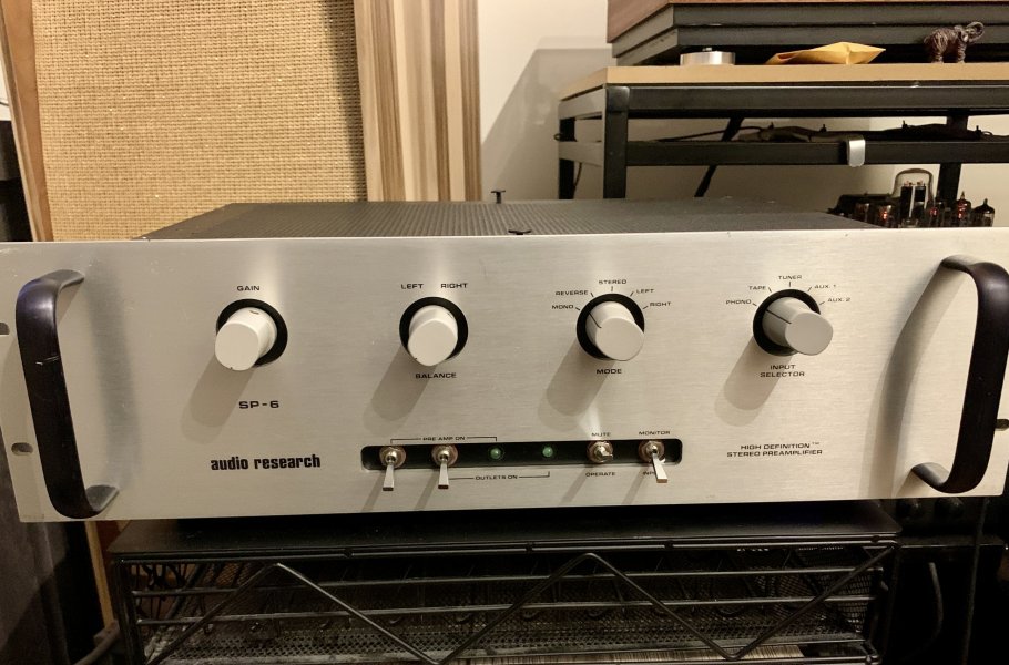
I was thinking of redoing at least the signal cable to stock with 18 or 20 AWG 4 conductor shielded cable (color coded). This is what ARC told me was used stock. I have the schematic and its a fairly easy job except the boards have no labels. example the selector & mode switch. I could just copy the existing cable hook up, but I'm not sure if the previous did 100% correct. then I'd be copying errors. maybe that's why the stereo reverse mode only outputs one side? or maybe the switch is dirty or broken? does anyone own a SP-6A? can someone take detailed pics of the inside near the rear panel where the RCA connectors are? and the pc board where the gain, mode and selector pots are? top and bottom. this would help. i can wire some paypal money for anyone who can help me out with this.
Thx.
I have an SP-6A I purchased used. The previous owner says he got it from an estate sale. The unit had the electrolytics recapped about 10 yrs ago. All works well except for the MODE selector. In Stereo Reverse Mode, only the the left side outputs sound. the other thing I find odd is all the wiring was replaced with solid core twisted pair. mostly the signal wires. but also some of the power wires. The guy who did this didn't do a very good job. very messy. not twisted neatly and routed any which way. Sacrilege!. Lol..
I was thinking of redoing at least the signal cable to stock with 18 or 20 AWG 4 conductor shielded cable (color coded). This is what ARC told me was used stock. I have the schematic and its a fairly easy job except the boards have no labels. example the selector & mode switch. I could just copy the existing cable hook up, but I'm not sure if the previous did 100% correct. then I'd be copying errors. maybe that's why the stereo reverse mode only outputs one side? or maybe the switch is dirty or broken? does anyone own a SP-6A? can someone take detailed pics of the inside near the rear panel where the RCA connectors are? and the pc board where the gain, mode and selector pots are? top and bottom. this would help. i can wire some paypal money for anyone who can help me out with this.
Thx.


.jpg")