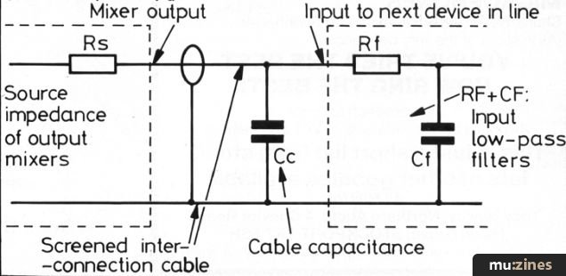
Interconnects as RCL Filters

Ron Resnick

Site Co-Owner, Administrator
Jan 24, 2015
16,219
13,681
2,665
Beverly Hills, CA
I give credit to Carlos269 for making this very correct point on a different thread:

The problem is as you start to link each component together each connection forms a RLC filter from the source component’s output impedance, the interconnecting cables’ electrical characteristics, and the next, down the audio chain, component’s input impedance.

As I've written in detail elsewhere I think it's very difficult to predict in advance which cable a particular audiophile is going to prefer between any two particular components in his/her own particular system.

This, incidentally, is why I am skeptical of "whole loom" cabling of a system with one model from one brand of cable. The "whole loom" concept is easy and psychologically comforting, but I'm not sure it's sonically valid.
 
  • Like
Reactions: lordcloud

sbnx

Well-Known Member
Mar 28, 2017
1,207
1,361
290
Nice! Nothing that will divide the 1's and 0's like a good juicy cable discussion. So why not just jump right in.

As you pointed out there are basically two camps. The Loom camp and the Flavor to Taste camp. I have not experimented enought to have a really valid opinion on this. I do trust the ears of the people I know that are in the Loom camp. So this is where I ended up. (There is really a third camp -- the "Cables Don't Matter" camp. But I don't think this is where WBF is at) I believe RG used to do some demos for large groups of people where he would have a mixed bag of cables and let people listen and then he would wire the whole system with the most inexpensive cable of the bunch. Apparently, it seemed obvious to people in attendance that the loom of the inexpensive cable sounded better. Some might argue this was staged. I don't know but I doubt it. (I was never at one of these demos so my comments about the demo are based on articles etc.)

From a scientific point of view we would just look at a cable from an RLC perspective. One could argue that since every cable has a differnt RLC then they would all sound different based on how that interfaces with the input impedance of some component. But I don't think so. There has to be some other factors involved that make certain cables sound the way they do.

For example the connectors and how the wire it terminated on the connector.
Chord company used to do this demo. They would have the same interconnect (Material, geometry, dielectric, shielding etc) where one was terminated with a very high quality metal RCA and the other was terminated with an RCA body made from PTFE. It was easy to hear the difference with the PTFE RCA sounding better.

Some cables sound very even while some highlight certain frequency bands. Some cables are noisy sounding and some cables really quiet. Some cables are "pure tone" and some have a lot of "bloom". I prefer a cable that is even, quiet and pure toned. But some actually would prefer the cable with bloom. To each their own. Pick a direction you want your sound to go and choose accordingly.
 

Carlos269

Well-Known Member
Mar 21, 2012
1,566
1,225
1,215
From a scientific point of view we would just look at a cable from an RLC perspective. One could argue that since every cable has a differnt RLC then they would all sound different based on how that interfaces with the input impedance of some component. But I don't think so. There has to be some other factors involved that make certain cables sound the way they do.
The factors are the electrical interactions of the upstream component’s output electrical characteristics, the interconnecting cables’ RLC specifications, and destination component’s input electrical characteristics. Simple as that. Ask an electrical engineer you work with to explain it to you.

For example the connectors and how the wire it terminated on the connector.
Chord company used to do this demo. They would have the same interconnect (Material, geometry, dielectric, shielding etc) where one was terminated with a very high quality metal RCA and the other was terminated with an RCA body made from PTFE. It was easy to hear the difference with the PTFE RCA sounding better.
Different materials have different parasitic RLC electrical characteristics which explain the above observations.
Some cables sound very even while some highlight certain frequency bands. Some cables are noisy sounding and some cables really quiet. Some cables are "pure tone"

Take any cable and install it between two different components and you will get different results from the same cable because it does not “act” on its own, it is subject to the electrical interaction with both the source and destination components.
 
  • Like
Reactions: Lagonda

Ron Resnick

Site Co-Owner, Administrator
Jan 24, 2015
16,219
13,681
2,665
Beverly Hills, CA
Take any cable and install it between two different components and you will get different results from the same cable because it does not “act” on its own, it is subject to the electrical interaction with both the source and destination components.
+1

(At least we can agree on the electrical fundamentals of cables, and the realities of cable selection! :D )
 
  • Like
Reactions: Carlos269

sbnx

Well-Known Member
Mar 28, 2017
1,207
1,361
290
So regardless of how I achieve it as long as two cables had the same R,L,C they would sound identical?

How small of a change do you think is audible? 0.1 femtofarad? Smaller?

In the end it doesn't really change anything since I don't know what R,L,C values are for various cables and there is not a table that I am aware of that says as R*C goes up then this is the resultant sound characteristic. And as L/C goes up this happens and so on and so forth.

It would be interesting to know the R,L,C of the Chord cable with the metal RCA connector vs. the PFTE body connector. I would think the difference would not be very much. Maybe I will ask Patrick if he has that info.
 

Carlos269

Well-Known Member
Mar 21, 2012
1,566
1,225
1,215
So regardless of how I achieve it as long as two cables had the same R,L,C they would sound identical?
If the parasitic R, L, C are taken into account then YES.
How small of a change do you think is audible? 0.1 femtofarad? Smaller?
Depends on the rest of the circuit.
In the end it doesn't really change anything since I don't know what R,L,C values are for various cables and there is not a table that I am aware of that says as R*C goes up then this is the resultant sound characteristic. And as L/C goes up this happens and so on and so forth.
You are not alone. Most cable designers do not even provide the electrical specifications of their cables like Canare, and Gotham Audio of Switzerland do. The professional-audio related cable manufacturers typically do. Most High-End Audio cable manufacturers dare I say don’t even measure, characterize or provide specifications for their cables.
It would be interesting to know the R,L,C of the Chord cable with the metal RCA connector vs. the PFTE body connector. I would think the difference would not be very much. Maybe I will ask Patrick if he has that info.
Please ask and post the complete electrical analysis the comparison underwent.
 

Neil.Antin

Well-Known Member
Jul 9, 2021
334
306
135
68
If you want to see what a single interconnect acting as an RCL filter looks like, use this calculator, just plug in the interconnect values and it will perform the transfer function and plot the bode diagram showing you the resonant peak (and cut-off frequency) RLC Low-Pass Filter Design Tool (okawa-denshi.jp). However, if you plug the values from say a Mogami Gold MOGAMI® - Bulk Patch Cables (mogamicable.com), the cut-off frequency is >10MHz, which is consistent with what Mogami publishes as attenuation >10MHz = 0.0608 dB/m. So, unless the interconnect has some really wild values, the RCL filter is forms is likely of limited concern. A much more difficult analysis could be to build a model of the entire stereo system with each interconnect and component modeled as a pole for a multi-pole filter.
 
  • Like
Reactions: Carlos269

Carlos269

Well-Known Member
Mar 21, 2012
1,566
1,225
1,215
If you want to see what a single interconnect acting as an RCL filter looks like, use this calculator, just plug in the interconnect values and it will perform the transfer function and plot the bode diagram showing you the resonant peak (and cut-off frequency) RLC Low-Pass Filter Design Tool (okawa-denshi.jp). However, if you plug the values from say a Mogami Gold MOGAMI® - Bulk Patch Cables (mogamicable.com), the cut-off frequency is >10MHz, which is consistent with what Mogami publishes as attenuation >10MHz = 0.0608 dB/m. So, unless the interconnect has some really wild values, the RCL filter is forms is likely of limited concern. A much more difficult analysis could be to build a model of the entire stereo system with each interconnect and component modeled as a pole for a multi-pole filter.
Precisely, as the number interconnections add up the compound effect is more pronounced. The impact of a single cable is limited, but heard as most everyone here will inform you.
 

Carlos269

Well-Known Member
Mar 21, 2012
1,566
1,225
1,215
If you want to see what a single interconnect acting as an RCL filter looks like, use this calculator, just plug in the interconnect values and it will perform the transfer function and plot the bode diagram showing you the resonant peak (and cut-off frequency) RLC Low-Pass Filter Design Tool (okawa-denshi.jp). However, if you plug the values from say a Mogami Gold MOGAMI® - Bulk Patch Cables (mogamicable.com), the cut-off frequency is >10MHz, which is consistent with what Mogami publishes as attenuation >10MHz = 0.0608 dB/m. So, unless the interconnect has some really wild values, the RCL filter is forms is likely of limited concern. A much more difficult analysis could be to build a model of the entire stereo system with each interconnect and component modeled as a pole for a multi-pole filter.
Furthermore, please remember that these modeling calculators use the Thévenin equivalent resistance (RTH) for the given circuit. Going further into the rabbit hole these circuits on the micro-scale are subject to reflected power fluctuations based on the different reactive loads of the cables, in combination with the next downstream component’s input electrical circuit characteristics.
 
  • Like
Reactions: Neil.Antin

Carlos269

Well-Known Member
Mar 21, 2012
1,566
1,225
1,215
If you want to see what a single interconnect acting as an RCL filter looks like, use this calculator, just plug in the interconnect values and it will perform the transfer function and plot the bode diagram showing you the resonant peak (and cut-off frequency) RLC Low-Pass Filter Design Tool (okawa-denshi.jp). However, if you plug the values from say a Mogami Gold MOGAMI® - Bulk Patch Cables (mogamicable.com), the cut-off frequency is >10MHz, which is consistent with what Mogami publishes as attenuation >10MHz = 0.0608 dB/m. So, unless the interconnect has some really wild values, the RCL filter is forms is likely of limited concern. A much more difficult analysis could be to build a model of the entire stereo system with each interconnect and component modeled as a pole for a multi-pole filter.
The effects on the electrical reactance of different cables cannot be discounted either.
 

Neil.Antin

Well-Known Member
Jul 9, 2021
334
306
135
68
Precisely, as the number interconnections add up the compound effect is more pronounced. The impact of a single cable is limited, but heard as most everyone here will inform you.

Furthermore, please remember that these modeling calculators use the Thévenin equivalent resistance (RTH) for the given circuit. Going further into the rabbit hole these circuits on the micro-scale are subject to reflected power fluctuations based on the different reactive loads of the cables, in combination with the next downstream component’s input electrical circuit characteristics.
I am not challenging that effect of cables on audio playback, only that as an RCL filter, the cut-off frequency should be so high that it should be insignificant. I have worked with the design of electromagnetic interference filters and within tolerances the calculations can be very accurate. But what becomes more problematic is the micro resonances in a system (we were measuring a system's PWM conductive emissions unfiltered every 1-Hz with sensitivity of micro-amps out past 50kHz with equipment not routinely available commercially). But, depending on the filter characteristics and the system resonant peaks (of which there were 100's of a range of just <4-Hz), the filter cut-off frequency undamped resonant peak could easily vary by >3dB, and if you landed on a particularly nasty system resonance the undamped resonant peak >40dB - and by experience before we understood how to measure the system, capacitors start failing. Whether this analogy applies to a stereo system - unknown.
 
  • Like
Reactions: Carlos269

Carlos269

Well-Known Member
Mar 21, 2012
1,566
1,225
1,215
I am not challenging that effect of cables on audio playback, only that as an RCL filter, the cut-off frequency should be so high that it should be insignificant. I have worked with the design of electromagnetic interference filters and within tolerances the calculations can be very accurate. But what becomes more problematic is the micro resonances in a system (we were measuring a system's PWM conductive emissions unfiltered every 1-Hz with sensitivity of micro-amps out past 50kHz with equipment not routinely available commercially). But, depending on the filter characteristics and the system resonant peaks (of which there were 100's of a range of just <4-Hz), the filter cut-off frequency undamped resonant peak could easily vary by >3dB, and if you landed on a particularly nasty system resonance the undamped resonant peak >40dB - and by experience before we understood how to measure the system, capacitors start failing. Whether this analogy applies to a stereo system - unknown.
Porting over power harmonics to audio reproduction playback systems is applicable but I would speculate that their effect on any individual node would be insignificant but as a compounded complex system they may very well be of significance as the ear is sensitive to 0.3dB perturbations.
 

Solypsa

Well-Known Member
Jun 7, 2017
1,811
1,401
275
Seattle
www.solypsa.com
Precisely, as the number interconnections add up the compound effect is more pronounced.
Question: when speaking of a compound effect vis a vis "interconnections" would this not also include, to some degree, all circuit connection junctions?
( iow those on the pcb or point to point circuit, which could add up to many hundreds )
 

Carlos269

Well-Known Member
Mar 21, 2012
1,566
1,225
1,215
Question: when speaking of a compound effect vis a vis "interconnections" would this not also include, to some degree, all circuit connection junctions?
( iow those on the pcb or point to point circuit, which could add up to many hundreds )
Since components are measured as a whole and their electrical specifications are provided, they can be treated as “black-boxes”. Yes, the internal interconnections matter and they are taken into account in the electrical specification of the component.

Individually, because of the close proximity distances and RLC’s involved these internal connections, whether on the PC boards or point-to-point, are insignificant but as you accurately stated they have a commutative and compounded effect that is accounted for in the overall components’ specifications.
 
  • Like
Reactions: Solypsa

Solypsa

Well-Known Member
Jun 7, 2017
1,811
1,401
275
Seattle
www.solypsa.com
Then it seems to me that an interesting solution would be to have a calibration point after each component's input where you could vary one ( or more ) LCR values until hitting a 'flat' response, thus making the long 'interconnections' part of the circuit too?
 

Carlos269

Well-Known Member
Mar 21, 2012
1,566
1,225
1,215
Then it seems to me that an interesting solution would be to have a calibration point after each component's input where you could vary one ( or more ) LCR values until hitting a 'flat' response, thus making the long 'interconnections' part of the circuit too?
It is best to address the overall resultant sound. A flat response is ultimately not desirable.
 
Last edited:

tony22

Well-Known Member
Nov 4, 2019
591
258
153
63
Bravo, Carlos, from another (retired electrical) engineer. All this stuff is incontrovertible, and basic, yet the only cable manufacturer I know of who clearly speaks in these terms is Gaelin Gaeris of Iconoclast. Kind of makes you wonder why practically all the rest don’t.
 
  • Like
Reactions: Carlos269

Solypsa

Well-Known Member
Jun 7, 2017
1,811
1,401
275
Seattle
www.solypsa.com
It is best to address the overall resultant sound. A flat response is ultimately not desirable.
OK. i get that ( I think ) from a holistic perspective. But do you want deviations from flat to be caused from within 'interconnections' or overall ( measured and defined per your example ) circuit topology?
 

Carlos269

Well-Known Member
Mar 21, 2012
1,566
1,225
1,215
OK. i get that ( I think ) from a holistic perspective. But do you want deviations from flat to be caused from within 'interconnections' or overall ( measured and defined per your example ) circuit topology?

As I’m not bound to the practice of connecting boxes together, in a trial and error fashion, and hoping for a desired outcome this becomes difficult to answer for those that use that approach, which is the majority of audiophiles.

Let me back up and start from the start. Let’s pretend that we live in an ideal world were each component measures flat from 20Hz to 20KHz and each interconnecting cable also measures flat from 20Hz to 20KHz, in the circuit, and the speakers also measure flat from 20Hz to 20KHz. If all these “flat” perfect components are assembled in a system and let’s say that the overall “system” level response also measures flat from 20Hz to 20KHz, then you would think that this would be ideal. But because of human hearing’s Fletcher-Munson loudness perception/sensitivity this “perfectly flat” system will sound bright and will not be pleasant to listen to.

So how do we go about achieving an “organic” sounding system with components that are designed to measure flat from 20Hz to 20KHz?

This is were the myriad of different items that audiophiles use for tone control come in: cables, room treatments, footers, isolation devices, coupling devices, mass-loading, and all the other things that are used to wrestle with the sound of the system.

As you can see, trying to arrive at a target sound is a stab in the dark using the traditional approach.

If you step back and think about it for a minute, like I have done, you then tell yourself there’s got to be a smarter way!

But on this response I will put the “Smarter way” approach to the side. I will do that because I have a fresh perspective on assembling a system and tuning it for the desired overall resultant sound. I have recently done this myself with my new reference system and I did it based on my learning of the smarter way approach. To answer your question head on:

do you want deviations from flat to be caused from within 'interconnections' or overall ( measured and defined per your example ) circuit topology?

To do this successfully as I have done with my new Ultimate horn system, the best place to implement the correction to the overall sound of the system is in the speakers’ crossover. Now bear in mind that the speakers now become optimized to achieve the desired overall sound of that specific system in that specific room. The speakers are no longer universal, they become a tailor made speakers for the system/room. This is analogous to what I do with my system-remastering, where I alter the overall system’s frequency response and polar response based on the resultant sound.

So there is my answer, if you follow the traditional approach of connecting random boxes together and want the most “effective” way to achieve the desire sound then you don’t take stabs in the dark with cables, room treatments, footers, isolation devices, coupling devices, mass-loading, and all the other things. If you want to achieve the goal you tune the speakers crossovers to target the overall sound that you’re after.

Having just said that, the system-remastering process is an elegant solution. Fine tuning the crossover is an iterative process that will drive the speakers design if the speaker design is fluid: my new reference horn system is currently a 6-way system that will go to a 7-way system next year. If you are dealing with a commercially off-the shelves speaker then obviously the crossover modifications will need to involve an analysis of the drivers’ operating & performance parameters.

I tried to answer this as concisely as possible and I hope that what I have stated is clear.

P.S. - The speakers with modified crossovers will obviously not be optimal with other system components/make-up or in other rooms if done correctly.
 
Last edited:

About us

  • What’s Best Forum is THE forum for high end audio, product reviews, advice and sharing experiences on the best of everything else. This is THE place where audiophiles and audio companies discuss vintage, contemporary and new audio products, music servers, music streamers, computer audio, digital-to-analog converters, turntables, phono stages, cartridges, reel-to-reel tape machines, speakers, headphones and tube and solid-state amplification. Founded in 2010 What’s Best Forum invites intelligent and courteous people of all interests and backgrounds to describe and discuss the best of everything. From beginners to life-long hobbyists to industry professionals, we enjoy learning about new things and meeting new people, and participating in spirited debates.

Quick Navigation

User Menu

Steve Williams
Site Founder | Site Owner | Administrator
Ron Resnick
Site Co-Owner | Administrator
Julian (The Fixer)
Website Build | Marketing Managersing