Strange bias setup..

Mr_H_UK

New Member
Jan 26, 2025
2
0
1
56
Uk
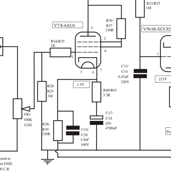
I have just rebuilt an amplifier, and seen this strange (to me) method of biasing the input stage.
The bias voltage is derived from the feedback resistance, and the current from the stage goes to the negative rail via the output transformer secondary.

Thoughts?
 

Attachments

  • Screenshot_20250126_192102_Samsung Notes~2.jpg
    Screenshot_20250126_192102_Samsung Notes~2.jpg
    85.4 KB · Views: 7
Hi,

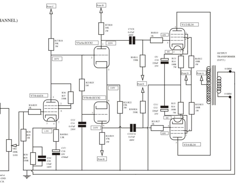
It doesn't really add much, except to show the return path via the output transformer secondary., but here you go.
 

Attachments

  • Screenshot_20250127_053525_Samsung Notes~2.jpg
    Screenshot_20250127_053525_Samsung Notes~2.jpg
    90.2 KB · Views: 5
Thanks for posting this!

By separating biasing and nfb application, very low resistance values can be used for the NFB network with a large compensation cap. Otoh, a huge electrolytic cap is now needed for decoupling.

Is it a worthwhile tradeoff where sound is concerned? Not obvious to me.
 

About us

  • What’s Best Forum is THE forum for high end audio, product reviews, advice and sharing experiences on the best of everything else. This is THE place where audiophiles and audio companies discuss vintage, contemporary and new audio products, music servers, music streamers, computer audio, digital-to-analog converters, turntables, phono stages, cartridges, reel-to-reel tape machines, speakers, headphones and tube and solid-state amplification. Founded in 2010 What’s Best Forum invites intelligent and courteous people of all interests and backgrounds to describe and discuss the best of everything. From beginners to life-long hobbyists to industry professionals, we enjoy learning about new things and meeting new people, and participating in spirited debates.

Quick Navigation

User Menu