Cable Theory

Thanks Sam and Jack :)
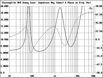
Amir, for amp to speaker might be worth thinking of what JA does at Stereophile (need to also read page 2):
http://stereophile.com/reference/60/

Still I would focus initially only on RCA between active products such as Source-Pre-Power.
The speaker cable challenge is going to be a real pig due to the range of other considerations, it is unlikely the interraction trend is identical between interconnect cables and speaker cables.
Cheers
Orb
 
Thanks Orb. That model was quite useful. I went ahead and put the initial one they proposed. The simulation seems to match their measured performance:
scan56.jpg

The above was measured using Audio Precision connected to the real circuit.

This is the simulation I ran, with the cable circuit included. What you see are two traces: one is the waveform as seen by the driver (the amplifier output). The other is right after the "cable" model but before the speaker model. The difference is the impact of the cable:

1084243849_SwrZv-X2.png


Looks like cable can make a difference. But wait! :) This is what happens when we reduce cable resistance by a factor of 10:

1084248360_RH3Vv-X2.png


As you see, substantial amount of difference disappears by just using a thicker cable with less resistance.

Next, I made the cable inductance 1/10th as much while keeping the resistance in there as it was:

1084255428_4rcTj-X2.png


As you see, it only makes a tiny difference in higher frequencies.

So at the end, we arrive at what we already knew :). That cable characteristics are dwarfed by the speaker, sans its resistance.
 
Gary

We may have to compare apples with apples ...
Let's have a more meanigful modelization, since our perceptions tend to be logarithmic or quasi-logarithmic. In what way do you think the cable you have mentioned would impact the FR of the speaker at 1 KHz? I will grant you that our ears can detect level changes of 0.1 dB.

The frequency response of the cable at 1kHz is far, far lower than 0.1dB. With the cable I mentioned, the resistance is 0.0016 ohms, impedance is 0.00377 ohms and is far below the output impedance of the amplifier and the input impedance of the loudspeaker.
 
Hi

Looks like using a thick welder-type cable would dispense one of thinking about cable differences, at least for speaker cables... Also Gary reply would suggest that the differences are smaller than 0.1 dB ... I am not very sure we are able to reliably discern such differences but I could be wrong ... ...Nah!!! I am not :)

Serious ly though.. It seems to me that in Interconnect cables there can be issues, especially in digital cables where the characteristic impedance is all over the place and with some manufacturers purposefully playing with the cable impedance for some "different" sound. The same seem to be happening with some "Audiophile" USB cables of course with the obligatory brutal price but whose characteristics seem to be far from USB standards.
 
Wow!! You guys have taken this theory to a whole new plane. I agree with Orb's line of reasoning - but let's initially focus on loudspeaker cables. Interconnects bring a whole different level of complexity.

I've been remiss in not discussing resistance:

The International Annealed Copper Standard is 1.589 ohms/1,000ft for 12AWG. But that is annealed copper, the high-purity copper wires we use (or should use) for hifi speaker cables is lower resistance at 1.565ohms/1,000ft. So, R1 and R2 in the simulation should be 0.001565 ohms. In Amir's simulation, 0.1ohms corresponds to about 31awg - tonearm wiring.


As you see, substantial amount of difference disappears by just using a thicker cable with less resistance.

Absolutely correct. The only reason I embarked on the cable quest is that as a loudspeaker designer, the objective me objected to the subjective mini-me hearing the difference in cables that absolutely should not have such a huge difference in the sound.

So at the end, we arrive at what we already knew :). That cable characteristics are dwarfed by the speaker, sans its resistance.

The moment any speaker cable goes above about 18awg, we reach the point where the resistance no longer becomes a factor. So, theoretically, every speaker cable 14awg and larger should sound identical, but unfortunately, I found it not to be so. This cable theory attempts to explain to myself why cables that should not measure any different can sound so vastly different.

Amir, one thing that your simulations show is that resistance has an inverse but linear relationship to the impedance of the loudspeaker. It is also inverse but linear to the output impedance of the power amplifier. Both of which is expected. ie. the higher the resistance of the cable, the higher the influence of the loudspeaker's impedance and the amplifier's impedance - and hence the "sound" of the loudspeaker and the amplifier. But once the cable is "competently designed" then it is almost a direct coupling between the output impedance of the amplifier and the input impedance of the loudspeaker.

Is it possible to with your software to look at the phase characteristics? I believe that what we hear are the time domain responses of the system of amplifier/cable/loudspeaker. Reason is that our hearing is far more sensitive to phase than to level as we discussed in another thread here:
http://www.whatsbestforum.com/showt...w-do-you-do-it-what-is-important-to-you/page3

We can resolve a time difference of less than 15us and we worked out that a 0.7deg in phase difference between the left ear and the right ear corresponds to a 4-inch shift in image at 10 ft.

Now, if we can hear the slight inductance and the slight capacitance of the cable results in a store/release of energy which corresponds to phase shift - and we can somehow simulate and/or measure the phase shift, then we are moving towards the confluence of objective and subjective.

I already know that the frequency response shifts are not measurable by any instrumentation I have. If the phase shift in the audible range is not measurable, we need to look elsewhere.... or admit defeat to the objectivists who say that cable does not make a difference.
 
Hi

Looks like using a thick welder-type cable would dispense one of thinking about cable differences, at least for speaker cables... Also Gary reply would suggest that the differences are smaller than 0.1 dB ... I am not very sure we are able to reliably discern such differences but I could be wrong ... ...Nah!!! I am not :)

You are not wrong - objective tests have shown that the threshold where average subjects can discern loudness differences is about 0.3dB at 200ms length. There is a lot of research in audiology and speech recognition into hearing threshold. What is interesting is that even with masking noise, the threshold does not change hugely - 1dB.

Serious ly though.. It seems to me that in Interconnect cables there can be issues, especially in digital cables where the characteristic impedance is all over the place and with some manufacturers purposefully playing with the cable impedance for some "different" sound. The same seem to be happening with some "Audiophile" USB cables of course with the obligatory brutal price but whose characteristics seem to be far from USB standards.

With interconnect cables, we also get into the area of galvanic noise, ground loops, etc. With single-ended cables, sometimes the ground is also tasked to provide the grounding for the entire system! I have found single-ended interconnects makes more of a difference than speaker cables in some systems, and almost no difference in others. The systems where the SE interconnects make a big difference are usually the ones where they are star-grounded via the signal path!!
 
Sure. Here is the simulation again with the resistors at the 1/10th value (.01 ohm) and the phase plotted relative to right vertical axis:

1084326728_tBhKX-X2.png
 
Oops. I just realized one of the inductors was left small. I changed it back to 0.6uh but it barely made a difference. I am too lazy to post it :).
 
Thanks for the reply, Gary. I hope you have a great time with your company :D Let me know what you think of TDR instruments relative to cable design and evaluation, when you get the chance.

Thanks! I'm having a great time, but this thread begs attention :D

For interconnects, time domain is certainly important. A time domain reflectometer can be extremely useful to show impedance mismatches. However, my philosophy to cable is design is to "do no wrong" and not to try to fix impedance mismatches in the system.

My figures in the first post were my attempts at a balanced minimum LCR for loudspeaker cables. Due to the characteristic impedance of loudspeakers, I don't know of any way to minimize time domain reflections in loudspeaker cables.
 
Oops. I just realized one of the inductors was left small. I changed it back to 0.6uh but it barely made a difference. I am too lazy to post it :).

Thanks, Amir. So, the difference that a cable with minimum capacitance and inductance makes very little of a difference to the speaker/amplifier interface.

What if we took a cable that is designed for minimum inductance, but high capacitance? I took one out of my stash and measured it - 0.01uH, 967pF.

If the +ve and -ve leads were widely separated, the cable would have maximum inductance but zero capacitance - theoretically, loop inductance would be 5.94uH.

Could we compare the response of the 3 cables?
 
Sure. Here is the simulation with .01uh and 967pf. I think the cap value is still way too small to make a difference in such low frequencies (note that the graph goes up to 50,000 Hz!)

1084368137_3yFcL-X2.png
 
This last last sentence of Gary's report confirms my experience.

"Intuitively, the dielectric soakage is also a form of storage of energy, hence, looking for a material that would not do this would result in a cable that would have better micro-dynamic detail."

My system has that micro-dynamic detail. My cables use a dielectric far thinner than Teflon.
 
Sorry that I have neglected this thread even though I am very interested. Just some questions (or maybe a red herring).

I notice that the cable is being modeled as lumped parameters: 1) voltage source -> resister -> inductor -> capacitor shunt to return conductor -> speaker. What is the justification for this?

At the same level of lumped-parameter modeling, one could: 2) put the capacitor before the resister and inductor...Or: 3) between them. Maybe I have it wrong, but aren't those different circuits?

Based on Kirchoff's Laws,
Circuit 1 gives Ztotal = ZL + ZR + ZC ZS/(ZC + ZS).
Circuit 2 gives Ztotal = ZC (ZR + ZL + ZS) / (ZC + ZR + ZL + ZS)
Circuit 3 ? haven't done.
Here, Ztotal is impedance seen by amp (which is assumed pure voltage source with no internal impedance) and V = I Ztotal.
ZR, ZC and ZL are the cable's lumped impedances for resistance, capacitance and inductance.
ZS is the complex impedance of the speaker.

All three of these cable models can't be right. In fact, none are!!!!!

PS Sorry about the lack of graphics.
 
Isn't this more a case of an answer in search of a problem?

More like no problem searching for no answer.

All my measurements, and now Amir's simulations confirm that the differences in phase and frequency response is far below audibility in any speaker cable. One that has "massive" capacitance (plenty of conductors in parallel) and "massive" inductance (two conductors spaced far apart) has within 20Hz to 20kHz range almost negligible phase and frequency response difference into a simulated and real loudspeaker load. Hence the objectivist view that cables make no difference.

However, in my journey over the past couple of years searching for the "perfect" speaker cable for demo-ing with at shows, I can consistently hear the difference between the various brands of speaker cables. Then, constructing my own, I can consistently hear the difference when using identical materials, changing the relative capacitance/inductance balance.

Where do we go from here? The perfect conundrum.
 
At the same level of lumped-parameter modeling, one could: 2) put the capacitor before the resister and inductor...Or: 3) between them. Maybe I have it wrong, but aren't those different circuits?

You are right, but the impedances are too small to make a difference in the audible range.
 
More like no problem searching for no answer.

All my measurements, and now Amir's simulations confirm that the differences in phase and frequency response is far below audibility in any speaker cable. One that has "massive" capacitance (plenty of conductors in parallel) and "massive" inductance (two conductors spaced far apart) has within 20Hz to 20kHz range almost negligible phase and frequency response difference into a simulated and real loudspeaker load. Hence the objectivist view that cables make no difference.

However, in my journey over the past couple of years searching for the "perfect" speaker cable for demo-ing with at shows, I can consistently hear the difference between the various brands of speaker cables. Then, constructing my own, I can consistently hear the difference when using identical materials, changing the relative capacitance/inductance balance.

Where do we go from here? The perfect conundrum.
At times like this, I'm reminded of the classic hit by The Toyes.
 

About us

  • What’s Best Forum is THE forum for high end audio, product reviews, advice and sharing experiences on the best of everything else. This is THE place where audiophiles and audio companies discuss vintage, contemporary and new audio products, music servers, music streamers, computer audio, digital-to-analog converters, turntables, phono stages, cartridges, reel-to-reel tape machines, speakers, headphones and tube and solid-state amplification. Founded in 2010 What’s Best Forum invites intelligent and courteous people of all interests and backgrounds to describe and discuss the best of everything. From beginners to life-long hobbyists to industry professionals, we enjoy learning about new things and meeting new people, and participating in spirited debates.

Quick Navigation

User Menu