Gradient 1.4 Speakers: Downsizing, Simplifying, and Changing

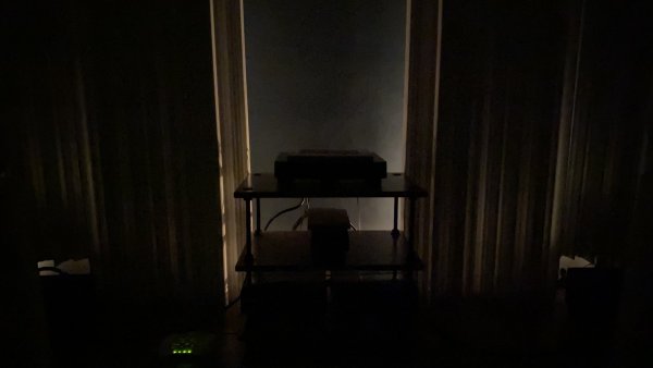
I've mentioned many times over the years in this thread and others that at night I like to listen to music in my stereo room in semi-darkness. I also mentioned in a prior post of this thread that I've finally achieved a very pleasing low-light "glow" without distractingly bright hot spots. With my new P.I. Audio Group AQD1 Quadratic Residue Diffusers (the new name for these now showing up on the company's temporary website), most of the light comes from two four-watt incandescent bulb night lights plugged into regular wall outlets (not my dedicated audio outlets) behind the Diffusers which are on the wall behind the speakers. Those night lights are also behind 8.5" x 11" black vinyl sheets (such as the vinyl which forms the covers of soft-backed ring binders) to block any direct hot spot from the bulb and bulb shade.

I've blacked out (with bits of electrical tape) most of the equipment running lights, with the only visible indicator lights being those on the router on the floor which feeds the Lumin X1 a wired ethernet signal. For some reason I don't find those four little indicator lights distracting so I haven't covered them up.

Up until now, I haven't had a camera which was up to the task of capturing the glow effect this lighting produces to my dark-accustomed eyes. Over the holidays, however, my wife and I got new iPhone 11Pro Max phones. The Night Mode of the camera in these phones is getting closer to being able to capture the effect. Two photos appear below. The actual effect is between these two efforts in brightness, closer to the dimmer one, but the brighter one gives you a better orientation of what you are looking at. The white Diffuser panels are a bit translucent even with only four-watt light bulbs behind them (and those behind the black vinyl sheets), and there is also some light leakage between and around the panels.
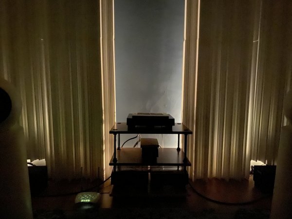
IMG_7316.jpg

IMG_7321.jpg
 
Another tweak to the acoustics of the room. As you see from reading posts 10, 11, and 12 above, I waffled about the treatment of the ceiling for best results with the Gradient 1.4s, alternating between putting absorptive foam, dispersive polystyrene, or just nothing to treat the first reflection areas of the speakers on the ceiling as viewed from the listening position. I eventually concluded that no treatment at all was the best solution for the ceiling.

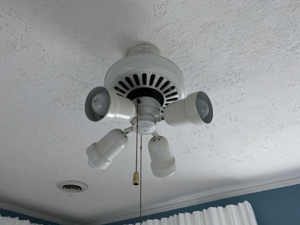
Further experimentation convinced me that what I've been reacting to is not so much the effect of the acoustic treatments on the ceiling reflection, but the presence of and reflections off of the fan blades themselves. The six large ceiling fan blades are themselves right about in the first reflection area. That's why I was able to effect such changes in the room acoustics by placing foam atop the fan blades. With prior speakers in this room, putting absorption in the form of 4-inch-thick Sonex panels atop the fan blades definitely seemed to help the image stability and staging.

What opened my eyes and ears to this fan blade effect was experimenting with the orientation of the fan blades. When the fan is not operating (I never use it since I've had the Sonex panels up there atop the blades for most of the time I've used this room for audio) I can manually position the blades however I want them with respect to the speakers. I had been using an orientation which pointed two adjacent blades roughly toward the two speakers. Then I recently tried an orientation which pointed on blade toward the center--toward the equipent rack--which pointed the blades adjacent to that on to spots outboard of the two speakers.That orientation instantly produced greater center image stability and and slightly more laterally expansive stage. However, it also created slightly more of the vertical venetian blind effect which has always been slightly audible in this room with all the speakers I've had in this room when moving my head from side to side from the listening position.

That was the "Aha!" moment. All I needed to do was to remove the fan blades. That's a simple operation requiring only a Phillips screwdriver since each blade is held to the rotating hub only by two Phillips screws. It took about 10 minutes to remove the blades. Bingo! The best center image stability I've ever achieved in this room, more lateral expansion, and the vertical venetian blind effect I heard when moving my head from side to side forth from the sweet spot was totally eliminated! Here's a picture of the ceiling light/fan sans fan blades; contrast this picture with the one in post #10 above which shows the fan blades and the absorbing foam the blades are supporting near the ceiling:

IMG_7326.jpg

I'm now wondering, however, whether I should again experiment with acoustic treatments on the ceiling. That is now tougher than it may at first appear, however. The fan blades made supporting absorbers or diffusers up there quite easy and temporary. Since, as you can see, the ceiling is not a smooth finish, velcro may not stick very well. And since it is a plaster ceiling, driving nails or staples into it is not easy, especially with the delicate lightweight white foam absorbers and polystyrene diffusers I have. Then, if I don't like the results, or even if I just want to reorient the ceiling acoustical treatment a bit, the ceiling will be marred even if the absorbers or diffusers are not.
 
I'm now wondering, however, whether I should again experiment with acoustic treatments on the ceiling. That is now tougher than it may at first appear, however. The fan blades made supporting absorbers or diffusers up there quite easy and temporary. Since, as you can see, the ceiling is not a smooth finish, velcro may not stick very well. And since it is a plaster ceiling, driving nails or staples into it is not easy, especially with the delicate lightweight white foam absorbers and polystyrene diffusers I have. Then, if I don't like the results, or even if I just want to reorient the ceiling acoustical treatment a bit, the ceiling will be marred even if the absorbers or diffusers are not.

Has anyone measured your listening room? I'd be a good idea to start from there and know exact mods in there.
 
If you mean "modes," measurable bass modes have nothing to do with the imaging, staging, or vertical-venetian-blind effects I'm hearing and describing here. Such effects are way above the bass range. In any event, I challenge anyone (even Bob Carver) to significantly correlate frequency response measurements with subtle imaging, staging, and other spatial effects.

Immediately prior to the Gradient 1.4s, I was using the DSPeaker Anti-Mode X4 equalizer with my Harbeth M40.2 speakers in this room. My X4 thread describes my considerable experience with audio equalizers and frequency response measurement equipment.

This room is actually very good in most respects compared to most other rooms where I've had audio systems. It's primary weakness is that the small size of the room prevents me from pulling the speakers far enough away from the wall behind them to allow the full development of depth of field. When I had an audio system in my downstairs living room I effectively had no wall behind the speakers since that "wall" opened up through double doors between the speakers into an adjoining open-floor-plan area and the depth of field obtainable there was of the type which made the brass of orchestras sound like they were coming from the next county.
 
If you mean "modes," measurable bass modes have nothing to do with the imaging, staging, or vertical-venetian-blind effects I'm hearing and describing here. Such effects are way above the bass range.

True. Modes were mentioned as realistically those can suck a fair chunk of joy from any setup and room. But if you have this sorted, that's great!
 
In post #15 above I talk about making sure that the screws holding the midrange driver and back plate to the spherical enclosure are tight once you've removed the grills. I mentioned that I heard a bit of buzz coming from the speakers and that it could have been either the grills or loose screws causing the buzz.

With further listening and perhaps further shrinkage of the cabinet materials as they've dried out during the winter months in Chicagoland, I've determined that at least part of the buzz comes from loose screws. The buzz reappeared weeks after I did my initial screw tightening following the removal of the grills. The grills have been off ever since their initial removal, so I knew it couldn't be from the Gradient 1.4 grills.

Sure enough, some of the 12 screws holding the midrange driver and back plate to the spherical enclosure had again become somewhat loose. Not sloppy loose, but enough so that I didn't have to torque the screws much to tighten them at least 1/4 turn. Torquing down all the screws uniformly again eliminated the buzz and indeed clarified the sound generally: I noticed blacker blacks, smoother and airier top two octaves, better more stable imaging, and better staging.

This is not the first time I've encountered speakers where the screws holding the drivers to the baffle really need periodic tightening for best sound and to prevent buzzing. Ones that come immediately to mind include my Gradient 1.5 Helsinki speakers, especially as to the midrange and tweeter driver screws. My Linkwitz Orion was VERY finicky about the tweeter driver screws buzzing if not tightened properly and this needed tending at least once a week--an annoyance. And the B&W 801 Matrix Series II woofer screws were amazingly sensitive to proper tightening for best bass sound--they had rubber grommets around them which needed to be compressed just so.

My other Gradient speakers, the Revolution Active and the 1.3, did not have any problems with screws becoming loose. That's even though Gradient's description of the new 1.4 mentions that it shares the same enclosure material with the old 1.3.

If you're as anal about such things as I am, you may want to invest in a mini-torque wrench as I have just to make sure you aren't over-tightening things while at the same time ensuring that you are equally tightening each set of screws. The tool I use is the Wheeler Firearms Accurizing Torque Wrench or Wheeler FAT Wrench for short. At least for my Gradient 1.4 speakers, even if you don't use a torque wrench, you will need a Torx T-20 bit to properly fit the screw heads.

If your drivers have any tendency to buzz, you will probably notice it easier on test tones than with music. For one thing the bass test tones last for awhile and thus allow you to track down whether the buzz is coming from room contents, part of the room structure (sometimes studs, pipes, or conduits inside a wall are the culprits), from a blown driver, or just from some part of the speaker enclosure such as loose driver screws. I use the test tones on any one of Stereophile's test disks. These are warble tones which go for about 15 seconds each around defined frequencies. Turn up the SPL of the test tones so that the SPL approximates your usual music listening volume. Once you hear the buzz with the warble tone of a particular frequency, put that tone on repeat until you can determine the origin of the buzz/rattle. In my case, just touching the back plate of the spherical enclosure or the flange area of the driver was enough to change or eliminate the audible buzz so that I knew that the extraneous noise was indeed coming from the enclosure. Applying some tightening eliminated the buzzing.

How tight should you make the screws? With both the Gradient 1.5 and the new 1.4, not too much torque is needed. And to prevent ruining the screwhead, stripping the screw or socket threads, or shearing/breaking the screw, you should not act like a gorilla with such tasks. I usually have success with the amount of torque I can apply comfortably using a two- or at most three-fingered grip on the screwdriver barrel.

Then I set the FAT Wrench to approximate that amount of torque. Then I loosen all the screws a whole turn or so and then tighten them all again using the FAT Wrench's calibrated torque to even up the torque on all screws. If you want to get really anal about it, initially set the FAT Wrench for about 1/3 of the target torque and apply just that amount to each screw, alternately working on opposite sides of the driver or back plate. Then do the same with 2/3 of the target torque, and finally full target torque. If using the FAT Wrench, a final target torque of 20 inch-pounds should be plenty tight.
 
Last edited:
I have found that the uniform screw tightening technique described in my prior entry has a surprisingly positive sonic effect, at least on my pair in my system.

Atte Salmi at Gradient doesn't think the screws need to be very tight at all, but I think this is really a valuable tweak in terms of further improving imaging, staging, and especially high frequency smoothness.

I use the Walker Firearms Accurizing Torque Wrench (aka FAT Wrench) to do this and use a setting of 20 inch/pounds for the final tightening. At least on my pair (which may not be typical in terms of tolerances of the cabinet and driver shapes--who knows?), about that amount of torque is needed to get the back plate and rim of the driver to cinch up with the edge of the enclosure cut-outs all around. Atte Salmi seems to think that all you need is the amount of torque necessary to get the screws flush with the backplate or driver rim. But there may be some language problems in this communication. Here is what Atte said in English (he is Finnish):

"Regarding the torque, it is very small number. Our torque meter goes down to 44 IN/LB but the torque is less and we cannot measure it with the tool. I can only say that the small Makita battery screw drivers which we use at production have scale from 1 - 18. For the coaxial driver we use number 12 and for the woofer number 8. This is not very scientific, but gives you some insight about the torque we use. Tell Tom Mallin not to tighten the screws too much. Correct amount is when the screw head has reached the surface of the driver chassis. After that the screw will just drill the hole and finally loosen."

I have found the screws loosening continually over the winter until I applied the 20 inch/pounds I mentioned. When they loosen, there is a bit of a loss of focus and occasional buzzing on bass tones in music or test tones. I've had similar issues with driver buzzing in the past on the Gradient 1.5 and Linkwitz Orion, among others. The FAT Wrench worked to correct the problems with those speakers as well.

The 1.4s are great sounding without this tweak. With it, they are astounding in terms of naturalness. Even the bass range seems both warmer and with yet less room-resonance-induced coloration in the midbass. When all these screws are uniformly tightened, these speakers are even more amazing in terms of imaging, staging, clarity, and freeedom from high-end brightness/fuzz/blur/edginess.
 
Now that I've "discovered" the importance of uniformly tightening the mounting screws, I'll add a further thought about how this affects the angling of the spherical head units.

As discussed above in post #16, in order to angle the head units directly toward my ears, I angle them back by four degrees. This angle is measured by using the Measurement>Level function of my iPhone 11 Pro Max. I put the top edge (the only truly flat edge of the phone) against the perforated back panel of the head unit (the grill has to be removed for this) and read the angle of the back panel on the iPhone display. I adjust the tilt-back until the iPhone reads four degrees.

I've noticed that uniformly tightening the screws on my set of Gradient 1.4s has the effect of cinching that back panel down so that it uniformly contacts the cabinet edge all around. When this is done, the angle read by the iPhone can change since you have in fact changed the orientation of the back panel with respect to the spherical head unit. Since tightening the screws creates uniform contact between the back panel and the spherical driver enclosure, I believe the the angle measures the tilt-back angle more accurately if the uniform screw tightening procedure is done first, before you measure the tiltback angle.

In my case, the sonic results bear out this theory. Soundstage and image focus is further improved if the tilt-back angle is adjusted after the uniform tightening of the screws.

A word about the tilt-back angle: I have noticed some tendency for the sphere to "slip" in terms of the tilt-back angle over time. The slippage I noticed took the form of reducing the tilt-back angle from the chosen four degrees to something very close to zero degrees.

I think this may be caused by tending to adjust the tilt-back of the spheres without actually lifting the spheres up off the three little rubbery bumpers which hold them in place atop the bass bin. To prevent this slippage, I suggest lifting the spheres just a bit off the bumpers as you adjust the tilt-back (or toe-in) angle of the spheres, rather than attempting to slide them atop the bumpers into the selected position. For me, at least, this cured the tendency for the spheres to "slip" out of the intended orientation.

Why the slippage? I'm not sure, but there could be two factors at play. One is possible deformation of the rubbery bumpers which gradually resume their intended shape, moving the sphere into a different orientation than intended.

Another possible factor is vibration of the spheres and bass bin during play (and there is considerable such vibration with program material with heavy bass played at healthy volumes). Before I mounted the spheres atop the bass bins and just set them on the carpeted floor, I noticed a strong tendency for the spheres to assume a particular orientation with respect to the floor. They would tend to roll into that orientation. This is probably due to the placement of the heavy magnet structures within the spherical head units. The magnets probably are not exactly centered within the spheres and that causes the observed rolling. It might also cause some slippage of the sphere atop the rubbery bumpers in response to bass vibrations.

I will continue to occasionally check the tilt-back orientation for "slippage." For now, however, the "slippage" seems to have stopped after I adjusted the tilt-back by first lifting the spherical head units a bit as I changed the amount of tilt-back.
 
As a "COVID-19 Project" I undertook trying out different positioning for my Gradient 1.4 speakers and my listening position. I have long used the "Rule of Thirds (29% Version)" as discussed and calculated via the Speaker Placement Calculator on the NoAudiophile.com website as my basic positioning.

For these speakers, however, I felt that I could use a set-up which might yield greater subjective depth of field as well as a bit stronger upper bass and lower midrange for a warmer sound. I had noticed that moving my listening position back a foot or more added more heft in these ranges as well as the rest of the bass. Thus, I thought I'd try the Cardas set-up as described on the Speakers Placement Calculator page. The author says this about the Cardas set up:

"God bless Cardas and his crazy golden ratio obsession If you can't get your speakers to have a soul, this placement will bring it out in force. Great for classical and just about any listening. Only issues that come up here is that your speakers end up taking over the entire room. If you have a dedicated room it's a great starting point, but if you plan to use this room for anything else it's probably going to be a challenge to work just about any other furniture around the placement."

I wasn't sure what was meant by "soul," but it sounded interesting and this set up would bring my speakers out about a foot more from the wall behind them than the Rule of Thirds (29% Version) placement did, about 3.5 inches further apart, as well as moving my listening seat back about 15.5 inches. Thus, I figured this set-up might give me the extra depth of field and warmth that I sought.

My dedicated room's main wall (the wall behind the speakers) measures 132 inches, while my side wall is 161 inches. Plugging these figures into the calculator and looking at the Cardas positioning gives the following results:

Space Between Speakers 59.14"
Head to Main Wall 110.22"
Speaker From Main Wall 59.00"
Speaker from Side Wall 36.43"


This compares with the following measurments for the Rule of Thirds (29% Version) I'd been using before:

Space Between Speakers 55.44"
Head to Main Wall 94.70"
Speaker From Main Wall 46.69"
Speaker from Side Wall 38.28"


Result? Success! I like this a lot, at least for the short term. It does in fact give me more warmth and much more depth of field. I don't hear any anomalies further down in the bass. In fact, the mid and lower bass are stronger, but without any added lumpiness/unevenness. The overall sound is a bit "gutsier." Maybe that's what the writer meant by this set up adding "soul" to the sound. Thus, at least in my room, for these speakers, this seems to be a valid alternative set up. If I later hear any anomalies, I will tell all.

I worried that bringing the speakers out further from the wall behind them might bring them so far forward that the P. I. Audio Group AQD sound diffusers on the side walls might not cover enough of the first reflection area. But I hear no "splashy" artifacts. Besides music, my acid test for this sort of thing is the "clap track" test track on the Sheffield/XLO test disk. The goal is to make this sound through your speakers from your listening seat exactly the way it sounds through headphones: tightly centered monophonic sound of a single handclap with no following reverb or slap echo. In fact, this new set up resulted in a new record for the resemblance to the sound of this track via headphones: VERY, VERY close to the same sound, indeed! These Gradient 1.4 speakers in this room had already produced the best result on this test I'd ever achieved and now the sound is remarkably similar to the headphone sound. No other speakers in any listening room I've tested have sounded nearly this center focused and echo free.

Because the speakers are now about four inches further apart and since I've maintained an equilateral triangle set-up, I'm also listening a few inches further from the speakers, 59 inches versus 55.5 inches. This is surprisingly discernable, in terms of how the speakers look from the listening seat. They look a bit smaller yet, but the soundfield seems quite a bit larger yet.

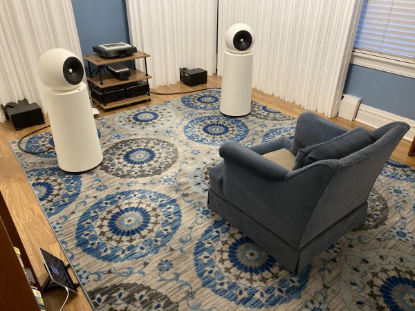
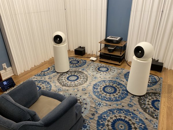
Here are a couple of pictures of the new set up.

IMG_7585.jpg

IMG_7586.jpg


Last edited:
  • Like
Reactions: Duke LeJeune
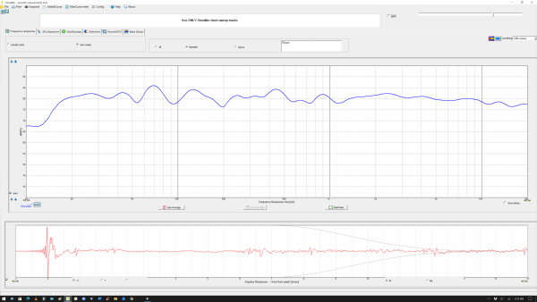
Finally, here is a casual measurement of this latest Cardas setup of the Gradient 1.4 speakers in my room. I say "casual" since I didn't use a tripod, didn't measure the exact position of the microphone, but simply rested the microphone with it pointing at the right speaker from a perch atop the back cushion of my listening chair. I put the mike atop two rolls of toilet paper atop that cushion to approximate my ear height when listening of a bit more than 34" above the carpet.

I used OmniMic V2 to make these measurements. Each vertical division of the graphs is 5 dB. The left end of the graph is 10 Hz, the right end is 20 kHz. No electronic equalization of any kind was applied to the speakers via Roon or otherwise to make these graphs. The smoothing is 1/6 octave. I adjusted the level of the Right Channel, Short Sine Sweep of the Omnimic test tone (track 12) so that the level was 80 dB at the microphone. I used OmniMic's default "blended" option for measuring frequency response.


Gradient 1.4 07-12-20 Right Channel Blended Omnimic 2.png
 
  • Like
Reactions: Marcus
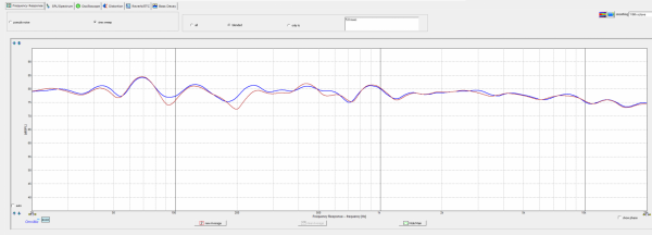
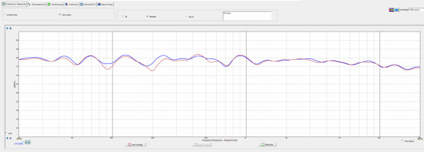
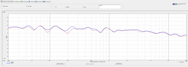
Okay, here are my "formal" measurements of this latest Cardas positioning setup of the Gradient 1.4 speakers in my room. I used my On-Stage Stands drum kit (short) tripod microphone stand with its boom arm positioned almost vertically and with the microphone aimed straight ahead at a point centered between the two speakers (30 degrees off axis to both speakers) with the microphone level and with the capsule at my listening height of 34 inches above the carpet. I moved the listening chair to the back of the room, as far as I could straight back from the microphone position to minimize comb filtering from the chair's physical bulk. With this positioning, the microphone capsule was 34 inches above the carpet, 66 inches from either side wall and about 110 1/4 inches from the wall behind the speakers.

As before, I used OmniMic V2 to make these measurements. Each vertical division of the graphs is 5 dB. The left end of the graph is 20 Hz this time, the right end is 20 kHz. The smoothing is 1/6 octave. I adjusted the Lumin X1's Leedh-processed volume control so that playing via Roon the Short Sine Sweep tracks of the Omnimic test disc (tracks 6 left channel, track 12 right channel) so that the level was 80 dB at the microphone at 1 kHz. I used OmniMic's default "blended" option for measuring frequency response. In the following graphs, the left channel is the blue trace, the right channel is the red trace.

This first graph is with no external electronic equalization applied:

Gradient 1.4 07-21-20 L+R.png

In the second graph, I have applied electronic equalization to the peak at 69 Hz (certainly caused by the room's floor-to -ceiling 8 foot, 6 inch dimension) using Roon's DSP engine. I used a parametric peak/dip filter, minus 5 dB, Q = 5, centered at 69 Hz:

Gradient 1.4 07-21-20 L+R 69 Hz EQ.png

Finally, in addition to squelching the 69 Hz peak, I also applied what I'm calling a Toole equalization. This creates a more-or-less straight and smooth slope down in response from 20 Hz to 20 kHz of about 10 dB. Toole and many of his acolytes believe that this sort of measured response at the listening position sounds best. To create this slope I used what Roon calls a high shelf parametric filter with some unusual parameters. The filter is minus 6 dB with a nominal frequency of 1 kHz and a Q of 0.2. That's right, not 2, but 0.2. For this graph I normalized the left and right channels at 75 dB at 1 kHz:

Gradient 1.4 07-21-20 L+R 69 Hz EQ + Toole EQ.png

Another way to implement this Toole filter would be to choose 625 Hz or 640 Hz as the inflection point rather than 1 kHz. That would put approximately the bottom five octaves of the audible range below the inflection frequency and five octaves above it. I tried 640 Hz, but so far I prefer the bit more treble that the 1 kHz inflection point provides.

Either way, application of what I'm calling a Toole filter certainly creates a more relaxed sound, one which ameliorates or eliminates the high frequency aggressiveness present in a lot of commercial recordings and one which is definitely more focused on the lower ranges without ever seeming bass heavy. I can certainly understand why many listeners prefer this type of balance.
 
Last edited:
  • Like
Reactions: Ron Resnick
My thanks to Robert E. Greene (REG of TAS) for pointing out that what really needed fixing in the Gradient 1.4 response in my room was the dip around 200 Hz. I guess since it was "only" about 5 dB, and since I have learned that filling in dips is often problematic where electronic equalization is concerned I was just going to live with that dip.

Closer examination of the response, however, by reducing the smoothing to 1/96-octave in OmniMic, showed that this was not one of those "infinite nulls" that are impossible to EQ away. It was difficult to attack with Roon's EQ at my present level of understanding of that function, however, since I haven't yet figured out how to apply different equalization to left and right channels. Note that, for some reason the dip in the 200 Hz area is of different size and different frequency in left and right channels.

After playing around with Roon's parametric EQ controls and looking at the results on the OmniMic 2 graph, I finally settled on a filter centered at 200 Hz, with a boost of 6 dB and a Q of 3. Once I listened to that from the sweet spot, I tweaked that to a boost of 5.6 dB. It is amazingly sensitive as to sounding like too much or too little heft in this region.

I also tweaked the 69 Hz band by narrowing its adjustment to a Q of 12, still with a reduction of 5 dB.

The combination of those two adjustments (putting aside for now, my "Toole filter") puts a good deal of well defined muscle on the sound of the Gradient 1.4s in my set up. Beefed up and toned up. Any remaining tendency toward a lean sound is gone, gone, gone. As usual, REG was quite right.

For REG's explanation of the importance of getting this part of the frequency spectrum right--and, according to him, most speakers do not get it right without equalization--is at this link.
 
Last edited:
  • Like
Reactions: Hamburger
Congratulations on accomplishing these two fixes!
 

About us

  • What’s Best Forum is THE forum for high end audio, product reviews, advice and sharing experiences on the best of everything else. This is THE place where audiophiles and audio companies discuss vintage, contemporary and new audio products, music servers, music streamers, computer audio, digital-to-analog converters, turntables, phono stages, cartridges, reel-to-reel tape machines, speakers, headphones and tube and solid-state amplification. Founded in 2010 What’s Best Forum invites intelligent and courteous people of all interests and backgrounds to describe and discuss the best of everything. From beginners to life-long hobbyists to industry professionals, we enjoy learning about new things and meeting new people, and participating in spirited debates.

Quick Navigation

User Menu