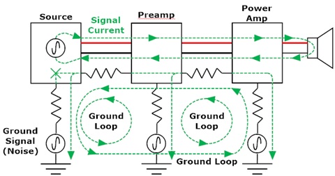
This article is to help show what causes those pesky ground loops many of us have had to deal with at one time or another. Essentially what happens is that a signal is created between two ground points in the system. The gain from source to speaker can be very high and amplifies the “ground” signal, leading to that familiar raspy buzzing sound.
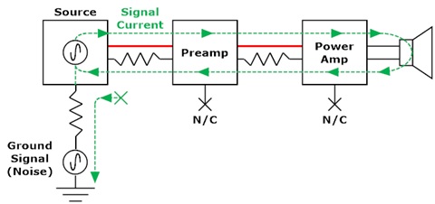
Consider the system shown below. Please note this is not meant to be technically rigorous but to illustrate how ground loops can form. Red lines are positive signal wires, black lines are negative signal wires, and dashed green lines show the current flow. The source (CD player, BD player, turntable, cable box, etc.) is connected to earth ground but the preamp and power amp “float”. This shows a system where only the source has a three-prong plug. The signal current can only flow one way and terminates at the single (source) ground terminal. Ground noise affects only the source, but since all components reference the source, the noise is suppressed. Any ground voltage at the source moves its (+) and (-) outputs equally. With no other ground connections the preamp and power amp follow. No ground loop, no nasty ground loop hum.
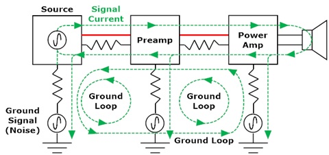
Now consider the case when all components have three-way plugs or are otherwise grounded. Now there are three ground loops formed: source to preamp, preamp to amp, and source to amp. Any ground leakage or noise current in any component can circulate among these loops. The currents through the resistors cause voltage fluctuations that affect each component. Since some of the signal current now goes into the ground loops, instead of the straight signal path shown above, the voltage induced is seen as signal by the components. They cannot tell if it is “true” signal voltage or voltage caused by ground currents. Since the ground current is often 60 Hz leakage from transformers or unbalanced loads that is the source of the 60 Hz (and harmonic) buzz commonly associated with ground loops. Note that any ground noise can cause this effect, whether 60 Hz power line signals or EMI/RFI.
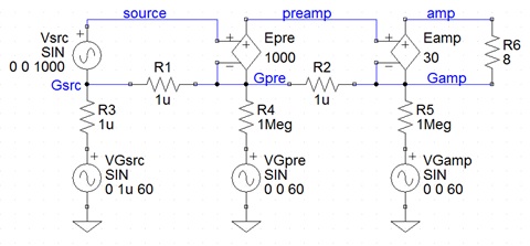
A simple simulation can illustrate the severity of the problem. Vsrc may be a turntable, CD player, cable box, etc. It is not used for these simulations thus its amplitude is zero. Notice the source ground, Gsrc, is connected to earth ground by another signal VGsrc. This represents the induced ground signal and is coupled to the source ground pin Gsrc through resistor R3. VGsrc is a 1 uV, 60 Hz signal representing induced ground noise. The preamp and amplifier (represented by ideal gain stages Epre and Eamp) are also connected to earth ground through resistors R4 and R5. Finally, signal grounds are connected through R1 (source to preamp) and R2 (preamp to power amplifier). The preamp has 60 dB of gain, the amplifier has 30 dB, and the 8-ohm load R6 represents a loudspeaker.
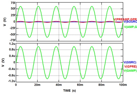
This example shows R1, R2, and R3 small (1 u-ohm), shorting the source, preamp, and amplifier grounds to the induced signal source VGsrc. They represent ideal cables and ideal source chassis ground. R4 and R5 are large (10^6 ohms) to float the preamp and power amp (e.g. two-prong power plugs). Because there is no low-impedance path to ground from the preamp and power amp, no ground loop is formed, as shown earlier. You can see this is the plot below; the signals are near 0 V at all points (f = femtovolt = 10^-15 V; u = microvolt = 10^-6 V). The top plot shows the source (blue), preamp (red), and amplifier (green) output signals. The bottom plot shows the ground signals at the source (blue), preamp (red), and amplifier (green). Even with only 1 micro-ohm there is some signal generated by the ground signal but it is very tiny (< 100 fV, or 0.000000000000001 V)
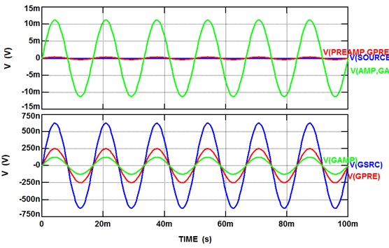
Now observe the results when R4 and R5 are also 1 micro-ohm, essentially shorting signal and earth grounds through tiny resistors. This represents the case when all components have three-prong plugs. The resistors act as voltage dividers to couple the signal grounds at each point in the chain. The 1 uVpk ground signal has been amplified to about 10 mVpk (about 6 uW) at the speaker. That would be about 36 dB SPL from a pair of 90 dB/W/m speakers 6’ (2 m) away. Still small, but what if the ground signal was 100 uV? That does not seem like much, but then the voltage across the speaker would be about 1 Vpk or about 62.5 mW. With a pair of 90 dB/W/m speakers the volume (SPL) six feet away would be about 75 dB, definitely audible (I would say loud!), and that is with no room gain. We have a ground loop; the signal ground goes one way, and chassis ground another, providing two places for the signal to flow. Now ground is not really ground so any ground signal is amplified, to our detriment.
Clearly small leakage or noise currents in the ground loops can cause very audible problems (as we know). Note cables typically have resistance of milli-ohms, not micro-ohms, and components may be plugged into different circuits so the ground path can be very long. Larger (parasitic) resistor values and additional ground signal sources will generate larger and potentially more complex noise as the signals interact among the components and with the primary signal from the source. Even low-level noise can often be noticed by its absence when the system is modified to eliminate ground loops.
HTH - Don
Consider the system shown below. Please note this is not meant to be technically rigorous but to illustrate how ground loops can form. Red lines are positive signal wires, black lines are negative signal wires, and dashed green lines show the current flow. The source (CD player, BD player, turntable, cable box, etc.) is connected to earth ground but the preamp and power amp “float”. This shows a system where only the source has a three-prong plug. The signal current can only flow one way and terminates at the single (source) ground terminal. Ground noise affects only the source, but since all components reference the source, the noise is suppressed. Any ground voltage at the source moves its (+) and (-) outputs equally. With no other ground connections the preamp and power amp follow. No ground loop, no nasty ground loop hum.

Now consider the case when all components have three-way plugs or are otherwise grounded. Now there are three ground loops formed: source to preamp, preamp to amp, and source to amp. Any ground leakage or noise current in any component can circulate among these loops. The currents through the resistors cause voltage fluctuations that affect each component. Since some of the signal current now goes into the ground loops, instead of the straight signal path shown above, the voltage induced is seen as signal by the components. They cannot tell if it is “true” signal voltage or voltage caused by ground currents. Since the ground current is often 60 Hz leakage from transformers or unbalanced loads that is the source of the 60 Hz (and harmonic) buzz commonly associated with ground loops. Note that any ground noise can cause this effect, whether 60 Hz power line signals or EMI/RFI.

A simple simulation can illustrate the severity of the problem. Vsrc may be a turntable, CD player, cable box, etc. It is not used for these simulations thus its amplitude is zero. Notice the source ground, Gsrc, is connected to earth ground by another signal VGsrc. This represents the induced ground signal and is coupled to the source ground pin Gsrc through resistor R3. VGsrc is a 1 uV, 60 Hz signal representing induced ground noise. The preamp and amplifier (represented by ideal gain stages Epre and Eamp) are also connected to earth ground through resistors R4 and R5. Finally, signal grounds are connected through R1 (source to preamp) and R2 (preamp to power amplifier). The preamp has 60 dB of gain, the amplifier has 30 dB, and the 8-ohm load R6 represents a loudspeaker.

This example shows R1, R2, and R3 small (1 u-ohm), shorting the source, preamp, and amplifier grounds to the induced signal source VGsrc. They represent ideal cables and ideal source chassis ground. R4 and R5 are large (10^6 ohms) to float the preamp and power amp (e.g. two-prong power plugs). Because there is no low-impedance path to ground from the preamp and power amp, no ground loop is formed, as shown earlier. You can see this is the plot below; the signals are near 0 V at all points (f = femtovolt = 10^-15 V; u = microvolt = 10^-6 V). The top plot shows the source (blue), preamp (red), and amplifier (green) output signals. The bottom plot shows the ground signals at the source (blue), preamp (red), and amplifier (green). Even with only 1 micro-ohm there is some signal generated by the ground signal but it is very tiny (< 100 fV, or 0.000000000000001 V)

Now observe the results when R4 and R5 are also 1 micro-ohm, essentially shorting signal and earth grounds through tiny resistors. This represents the case when all components have three-prong plugs. The resistors act as voltage dividers to couple the signal grounds at each point in the chain. The 1 uVpk ground signal has been amplified to about 10 mVpk (about 6 uW) at the speaker. That would be about 36 dB SPL from a pair of 90 dB/W/m speakers 6’ (2 m) away. Still small, but what if the ground signal was 100 uV? That does not seem like much, but then the voltage across the speaker would be about 1 Vpk or about 62.5 mW. With a pair of 90 dB/W/m speakers the volume (SPL) six feet away would be about 75 dB, definitely audible (I would say loud!), and that is with no room gain. We have a ground loop; the signal ground goes one way, and chassis ground another, providing two places for the signal to flow. Now ground is not really ground so any ground signal is amplified, to our detriment.

Clearly small leakage or noise currents in the ground loops can cause very audible problems (as we know). Note cables typically have resistance of milli-ohms, not micro-ohms, and components may be plugged into different circuits so the ground path can be very long. Larger (parasitic) resistor values and additional ground signal sources will generate larger and potentially more complex noise as the signals interact among the components and with the primary signal from the source. Even low-level noise can often be noticed by its absence when the system is modified to eliminate ground loops.
HTH - Don


