Re-Living My Past (OTL Vacuum Tube Builds)

Mark (Basspig) Weiss

Well-Known Member
Aug 3, 2010
688
49
1,590
New Milford, CT
www.basspig.com
Way back in the '60's I wanted to build a hi fidelity amplifier, but could not afford the output transformer of that quality. So I looked over several tubes that had low plate resistance and settled on the 8020/6AS7 back then and built an amp with 3 6AS7's. It put out 25W into 16? loads and was flat from 10-100,000cps, at least as best I could tell on my Heathkit oscilloscope of that era.

Well after repairing and upgrading a few Phase-Linear amplifiers for fellow audiophile clients, which pays well, I decided I still enjoy this hobby. I updated some of my test gear and have spectrum analyzers, distortion analyzers, all sorts of signal generators, meters, power supplies, frequency counters, oscilloscopes, etc.

So at this point, I have a strong desire to revisit my OTL vacuum tube amp design, update it a bit, increase the power.

So here's my thought. Using Circlotron topology (really just a fancy name for a push pull cathode follower output) and some ultra low plate resistance sweep tubes, a solid state power rectifier (power supply will be transformerless too, making this amp as dangerous as the 5 tube AC/DC radios of the 1950s) maybe opto-coupled input stage to isolate source components and a couple 12AT7s in the gain preamp stages. Similar to Futterman's designs. I'm looking at 6C33 tubes, but also find the 6P45 a very attractive alternative. Allen Kimmel claims he achieved 125W RMS into 8? with just four EL509 (6P45) beam tetrodes in the output stage. 200W peak (and then his power supply sagged). So four tubes per channel would give me a nice 125wpc with headroom to 200wpc.
EL509/6P45 can do 1400mA plate current at 140V plate potential, per tube. Plate resistance is 80? and can be forward biased to reduce that figure substantially. Kimmel's amp claims to have a .8? output impedance, for a damping factor of 10 into 8? speakers.
This will be the lightest tube amp of substance ever built, being not one piece of iron on the chassis. I even have ideas for powering the filaments (2 amperes a piece for the 6P45) without a transformer, if possible.
Another goal for this amp is to have all stages DC coupled. A lot of cathodyne drive circuits, cathodes directly feeding control grids of the next stage, etc. Only one cap at the input. The rest servo feedback balanced to keep the DC balance across the load.
It should be a fun project. Have to wait for some of my stuff to sell on ebay, then buy chassis, Magnovel tube sockets, 6P45 tubes (from Russia), some electrolytic caps for the power supply, etc. I have most of the rest of the tubes, resistors and other parts. Planning to run strips of 2oz copper PCB as ground bus all around the inside of the chassis for ground ties, terminated at the input jack.
This project is about having fun and meeting the 'no transformers' challenge I've set for myself, while producing a useable amplifier with decent power output.
 
Way back in the '60's I wanted to build a hi fidelity amplifier, but could not afford the output transformer of that quality. (...) I'm looking at 6C33 tubes, but also find the 6P45 a very attractive alternative. Allen Kimmel claims he achieved 125W RMS into 8? with just four EL509 (6P45) beam tetrodes in the output stage. 200W peak (and then his power supply sagged). So four tubes per channel would give me a nice 125wpc with headroom to 200wpc.
EL509/6P45 can do 1400mA plate current at 140V plate potential, per tube. Plate resistance is 80? and can be forward biased to reduce that figure substantially (...) .

Nice to know I am not alone. I was exposed to a Futterman OTL3 and later got into a DIY copy of it in the early 70s and since then OTLs were part of my life. Due to time and heat constraints some years ago I parted with a pair of the big Atmasphere MA2, that I have upgraded myself along several versions using advice and parts from Ralph Karsteen - a nice feature of his tubed point to point wiring OTLs!

If you want to go the EL509 route, you have to source NOS EL509's , that can be very expensive - current versions do not have the 1400mA capability - they are reported to do just 500 mA! :(
 
Hey Mark, where do you plan on acquiring the chassis from?
 
Hey Mark, where do you plan on acquiring the chassis from?

Antique radio has pretty good prices on Hammermill chassis. About $20 for the size I need to build a mono block.

As for the tubes, EL509s are expensive. I'd probably go with 6P45s, which are the Russian version, similar ratings, magnoval base.
 
Mark, so great to hear you are using your talents to help other music lovers and that it pays well to boot :) Looks like you're going to have a lot of fun with this project.

When you say dangerous, how dangerous? :)
 
Mark, so great to hear you are using your talents to help other music lovers and that it pays well to boot :) Looks like you're going to have a lot of fun with this project.

When you say dangerous, how dangerous? :)

Jack,
Using the mains supply in amplifiers without an insulation transformer means that your 0V line must floating - not grounded - and statically at neutral or phase voltage, or something between them. It is a very dangerous practice and strictly forbidden in Europe - you have a 50% probability of being electrocuted by the signal lines each time you connect the power cable, as power connectors are not neutral-phase labeled!
 
In other words, LETHALLY dangerous? Hot damn. :eek:
 
In other words, LETHALLY dangerous? Hot damn. :eek:

Could be if you use a non-polarized PC and plug it in so you are putting the hot side to the chassis.
 
I'm 100% sure Basspig will make sure he doesn't do that. Wonder though if the 0V line is always where it's supposed to be. Imagine if some work was done on the house electrical system and it got reversed somehow. Ouch.
 
I'm 100% sure Basspig will make sure he doesn't do that. Wonder though if the 0V line is always where it's supposed to be. Imagine if some work was done on the house electrical system and it got reversed somehow. Ouch.

Totally valid concerns, and the reason why we don't see ac/dc 5 tube radios anymore. Not totally lethal (I've been shocked a number of times while touching a radio chassis that was connected to a non polarized extension cord while standing on dirt floor in an unfinished cellar, way back when).

Some partial remedies would involve totally insulated chassis, maybe an optical isolator input, or, ultimately, for a commercial product, an isolation 1:1 transformer.

For decades going back, I lacked the shop facilities to build anything sophisticated, but now I have the shop setup that's beyond my wildest dreams in 1965, and can analyze things down to the smallest minutae, such as which interstage coupling caps give the lowest distortion. I have an analyzer now that can reliably read distortion levels to 1/10,000 of one percent.

But tubes are so much fun to design with, a joy to look at and photograph, and best of all, something I totally understand because that's all there was when I was growing up, so I learned it well.
 
For decades going back, I lacked the shop facilities to build anything sophisticated, but now I have the shop setup that's beyond my wildest dreams in 1965, and can analyze things down to the smallest minutae, such as which interstage coupling caps give the lowest distortion. I have an analyzer now that can reliably read distortion levels to 1/10,000 of one percent.
Sounds spot on! But that distortion accuracy feels a bit too precise: 0.0001% is measuring 120dB down. The makers of high precision opamps struggle to get readings that accurate ...

Frank
 
Sounds spot on! But that distortion accuracy feels a bit too precise: 0.0001% is measuring 120dB down. The makers of high precision opamps struggle to get readings that accurate ...

Frank

I was skeptical too, but Tektronix doesn't use op-amps in the low level circuitry. The AA501 analyzer can measure levels down to -180dB.
It's true that op-amps like LF353 have about .002% distortion per block. That would be unsuitable in test equipment.
 
Well, you got me going now, Mark. Found some spec's on that unit, and its capability is limited by the residual THD and noise of the unit itself. Which is in the range -90 to -100db, depending on frequency range. These are the sort of figures I was expecting ...

Why I mentioned opamps is that some of the latest audio examples are so good that it is somewhat difficult to measure how low their distortion is. The standard Audio Precision equipment and test procedures are not sensitive enough to register the levels, so they have to use a workaround to calculate it.

Frank

The distortion is limited by the fidelity of the test oscillator, actually. With the SG505 Ultra Low Distortion Oscillator, I can reliably measure distortion levels down to .0008%. With the SG5010, that gets things down to .0003%. Granted, the weighting filter has to be used to get down that low, and all cables have to be very short and well shielded. Just placing a hand near an unshielded twisted pair going from generator to analyzer introduces a huge increase in the distortion measurement.

My spectrum analyzer has a noise floor down around -94dBm and IT can't see any of the distortion that the AA501 can see down below .005%. There's a good 15-20dB more room to work with on the AA501 than on the HP 3580A. I can verify this with an oscilloscope connected to the Function Output of the AA501. There's good clean distortion biproducts there and not a lot of noise, when the input source is the SG505. Comparitively, digital sources have a lot higher distortion, about .01%, which surprised me. My cleanest signal source is an analog oscillator. When you are working with noise levels in the -120dB range, wiring must be treated as if it were carrying microwave signals. Short leads, proper shielding, etc.

One must be aware that Tektronix may publish a spec, but those specs are minimum performance. Typical units are an order of magnitude better. For instance, my DMM claims to be 1% accurate, but typical units in the field are demonstrated to have .1% accuracy. I have two FG501A function generators. Tek claims under 1% distortion. In practice, after calibrating them and tweaking the distortion adjustments, I've gotten them down to .075% THD over the entire audio band and still well under .2% at 2MHz. That's well under Tek's specification for distortion for that particular oscillator. As for the AA501, it has four digits past the decimal place. They wouldn't bother with the fourth digit if it were not possible to make measurements that small. ;)
 
One has to be careful not to confuse accuracy with measurement resolution: the fourth digit may be seen to alter in value depending on what you measure but it will have little meaning when attempting to assess distortion below 100dB. It would be impossible, for example, to get a valid reading of -180dB distortion: it may appear on the counter under some circumstance but would have no valid meaning.

Generally with electronics it's straightforward to get -80dB performance in some area, then you start having to be careful aiming for -100dB capability. Beyond that, in the -100 to -120dB range, you really have to apply yourself, start getting really fussy and particular about everything: this is where the movement of the hand becomes a factor, as you say, the absolute precision and integrity of shielding and grounding become paramount. Beyond -120dB is a nightmare world: if you wriggle your nose from the other side of the room the reading will double in value -- this is definitely a no-go zone for audio.

But if you can consistently do better than -100dB then there should be no worries: that's all the accuracy needed for best quality audio.

When playing with measuring gear one always has to be careful. A story I read somewhere, roughly compressed, goes like this: AVOmeters which were the ultimate in accuracy at one time were being flogged by a sales chappie. Went to a electronics company to demonstrate their superiority, by showing how much all the meters they had on site disagreed with each other. Only trouble was, they all did agree largely with each other and these readings were consistently different from the AVOmeter! The poor chap was thoroughly shaken, left sheepishly -- the manager didn't have the heart to tell him that a week earlier there had a major push to calibrate every meter in the place to agree with other, even the cheapies, for consistency; using what was considered the best meter at the time as the reference ...!!

Frank
 
Yup, lots of old stories like that.

Many folks may not know that that AA501 has a very sensitive RMS voltmeter built into it. One way of getting an idea of the dynamic range of the instrument is to plug an oscilloscope into the Function Output, and connect a signal source to the input of the analyzer. The voltmeter can be 'zero referenced' by pressing a button. For my test, I used an FG501A function generator to apply a +18dBm signal to the input. I switched to RMS voltmeter mode and zeroed the reference, so that +18dBm is effectively our baseline. Then I cutoff the input signal. The meter reads -127dB, unweighted. With 30KH LPF and 400Hz HPF, the reading decreased to -137dB. The scope shows a pretty flat line with very little noise in there.
By contrast, my LF353 op-amp has a noise floor of about -93dB below its clipping (rail potential) on this meter, mostly random white noise, as the scope reveals.
Traditional op-amps simply are not quiet enough for these types of applications. I believe that's why we find very unusual types of discreet devices in the front ends of instrumentation amplifiers, which often much have 140dB or better dynamic range in order for tests to be accurate.
 
Tonight, I have a 5998 dual triode putting out 10 watts into an 8? speaker. It's triode units are connected in parallel, and grids are direct driven (DC) by a 24Y triode. Output is cathode follower, capacitive coupled to a speaker.
When I come into some cash (have a UTC HA-107 transformer up on eBay for sale now), I plan to buy some used 6P45s and start building a push pull amplifier with negative and positive power supplies, fed by Schottky diodes for soft switching and lower noise. Presently, the 5U4 rectifier is loaded to the limit and voltage has dropped to about half the unloaded value. But the direct drive works great. Resistance coupled amps must die! :)
 
Way back in the '60's I wanted to build a hi fidelity amplifier, but could not afford the output transformer of that quality. So I looked over several tubes that had low plate resistance and settled on the 8020/6AS7 back then and built an amp with 3 6AS7's. It put out 25W into 16? loads and was flat from 10-100,000cps, at least as best I could tell on my Heathkit oscilloscope of that era.

Well after repairing and upgrading a few Phase-Linear amplifiers for fellow audiophile clients, which pays well, I decided I still enjoy this hobby. I updated some of my test gear and have spectrum analyzers, distortion analyzers, all sorts of signal generators, meters, power supplies, frequency counters, oscilloscopes, etc.

So at this point, I have a strong desire to revisit my OTL vacuum tube amp design, update it a bit, increase the power.

So here's my thought. Using Circlotron topology (really just a fancy name for a push pull cathode follower output) and some ultra low plate resistance sweep tubes, a solid state power rectifier (power supply will be transformerless too, making this amp as dangerous as the 5 tube AC/DC radios of the 1950s) maybe opto-coupled input stage to isolate source components and a couple 12AT7s in the gain preamp stages. Similar to Futterman's designs. I'm looking at 6C33 tubes, but also find the 6P45 a very attractive alternative. Allen Kimmel claims he achieved 125W RMS into 8? with just four EL509 (6P45) beam tetrodes in the output stage. 200W peak (and then his power supply sagged). So four tubes per channel would give me a nice 125wpc with headroom to 200wpc.
EL509/6P45 can do 1400mA plate current at 140V plate potential, per tube. Plate resistance is 80? and can be forward biased to reduce that figure substantially. Kimmel's amp claims to have a .8? output impedance, for a damping factor of 10 into 8? speakers.
This will be the lightest tube amp of substance ever built, being not one piece of iron on the chassis. I even have ideas for powering the filaments (2 amperes a piece for the 6P45) without a transformer, if possible.
Another goal for this amp is to have all stages DC coupled. A lot of cathodyne drive circuits, cathodes directly feeding control grids of the next stage, etc. Only one cap at the input. The rest servo feedback balanced to keep the DC balance across the load.
It should be a fun project. Have to wait for some of my stuff to sell on ebay, then buy chassis, Magnovel tube sockets, 6P45 tubes (from Russia), some electrolytic caps for the power supply, etc. I have most of the rest of the tubes, resistors and other parts. Planning to run strips of 2oz copper PCB as ground bus all around the inside of the chassis for ground ties, terminated at the input jack.
This project is about having fun and meeting the 'no transformers' challenge I've set for myself, while producing a useable amplifier with decent power output.

Hi. I just stumbled upon your posting. I'm a bit of an OTL addict myself; I have four that I've built already, and I am starting to plan my 5th. For my most recent construction (number 4), I decided, just for the hell of it, to make it totally transformerless, like the one you were talking about. Mine uses 6082 output tubes (four per channel) in a totem-pole configuration. The heaters are rather ideal for direct mains operation, being 26.5V at 0.6 amps, so four of them plus input and drive tubes works out about right for the US mains voltage.

About safety, honestly I think people tend to exaggerate the dangers of direct mains connections, especially with the tired old "what if it were plugged in the wrong way round" sort of objection. First of all, one obviously will use a polarised plug these days, and also check the mains socket for correct wiring before using it. In my amp the chassis is connected to true ground, and the signal ground is the mains neutral. Neutral is never more than a few hundered millivolts away from true ground, in my experience. For added safety I have a hefty 35A bridge rectifier, with "outputs" shorted together, connected between chassis and signal ground. This limits the chassis/signal ground voltage difference to 2 x 0.7 = 1.4 V max. This ensures that if the amp were ever plugged into a mis-wired mains socket, it would blow the fuse at the main junction box and prevent any other damage. Of course, the signal source needs to be "floating" so that its signal ground can be connected to the amplifier's signal ground without getting a hum loop, but that is usually no problem with a typical CD player, which is usually double-insulated with just a 2-prong power socket.

Anyway, I'm curious to know whether you ever built the amplifier you were talking about in this thread...

BTW, I notice you said you're planning to make it a circlotron. I thought about that, but I couldn't see any way of achieving it with a totally transformerless design, since the circlotron needs floating power supplies. That's why I settled on a totem-pole for mine.

Chris
 
Last edited:
Hi. I just stumbled upon your posting. I'm a bit of an OTL addict myself; I have four that I've built already, and I am starting to plan my 5th. For my most recent construction (number 4), I decided, just for the hell of it, to make it totally transformerless, like the one you were talking about. Mine uses 6082 output tubes (four per channel) in a totem-pole configuration. The heaters are rather ideal for direct mains operation, being 26.5V at 0.6 amps, so four of them plus input and drive tubes works out about right for the US mains voltage.

About safety, honestly I think people tend to exaggerate the dangers of direct mains connections, especially with the tired old "what if it were plugged in the wrong way round" sort of objection. First of all, one obviously will use a polarised plug these days, and also check the mains socket for correct wiring before using it. In my amp the chassis is connected to true ground, and the signal ground is the mains neutral. Neutral is never more than a few hundered millivolts away from true ground, in my experience. For added safety I have a hefty 35A bridge rectifier, with "outputs" shorted together, connected between chassis and signal ground. This limits the chassis/signal ground voltage difference to 2 x 0.7 = 1.4 V max. This ensures that if the amp were ever plugged into a mis-wired mains socket, it would blow the fuse at the main junction box and prevent any other damage. Of course, the signal source needs to be "floating" so that its signal ground can be connected to the amplifier's signal ground without getting a hum loop, but that is usually no problem with a typical CD player, which is usually double-insulated with just a 2-prong power socket.

Anyway, I'm curious to know whether you ever built the amplifier you were talking about in this thread...

BTW, I notice you said you're planning to make it a circlotron. I thought about that, but I couldn't see any way of achieving it with a totally transformerless design, since the circlotron needs floating power supplies. That's why I settled on a totem-pole for mine.

Chris


I think we're on the same page about these safety issues. For personal use/experimentation, it is fine, since I control the wiring in this building and it is conformant to NEC standards.
My approach is also to use 3-prong grounded plug, with the fuse taking up the slack if an outlet is reverse-wired hot/neutral. Current would flow to earth ground and the fuse would open in the case of miswired outlet.

Input isolation was achieved by means of true differential input stage. The CMRR is excellent and it works.

I am having some issues with making Circlotron work with the transformerless power supply. I've worked around some of them by using a simpler rectifier design and voltage doubler circuits. I have four power supply rails per channel on this amp.

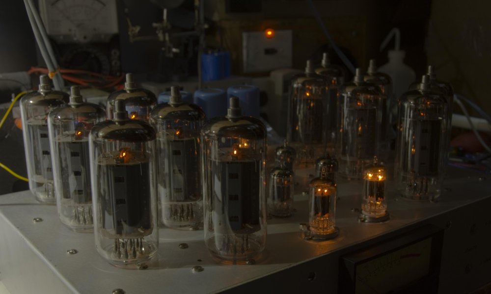
Here is an early photo from last fall when I was testing the filament power supply. I'm using a TRIAC to power the 6P45s and series string with ballast resistor for the low power tubes. I may implement a DC filament for the first preamp stage at some point, depending on noise levels.

NIK_8717.jpg

I'm working toward a goal of end of March readiness for the amp, so I can show it at the next Basspig Audiophile Society Social meeting this coming spring. This is purely for fun.

I'm posting updates at my business page on Facebook: https://www.facebook.com/AmplifierExperts
 

About us

  • What’s Best Forum is THE forum for high end audio, product reviews, advice and sharing experiences on the best of everything else. This is THE place where audiophiles and audio companies discuss vintage, contemporary and new audio products, music servers, music streamers, computer audio, digital-to-analog converters, turntables, phono stages, cartridges, reel-to-reel tape machines, speakers, headphones and tube and solid-state amplification. Founded in 2010 What’s Best Forum invites intelligent and courteous people of all interests and backgrounds to describe and discuss the best of everything. From beginners to life-long hobbyists to industry professionals, we enjoy learning about new things and meeting new people, and participating in spirited debates.

Quick Navigation

User Menu