
Yes, theoretically perfect tubes…not real ones that perform worse. Your amp measures a lot like an imperfect simulation of a differential input and push pull output..As best we can figure, when Bascomb did that measurement 23 years ago, he grounded one of the speaker terminals. This is very easy to do with most test equipment! That unbalances the drive to the power tubes so distortion takes off pretty fast. Typically the MA-1 can make about 1% at full power and if you are careful with the tubes you can get it down to 0.5%.
To properly measure the distortion you need a differential probe at the least so you can look at the balanced output.
I've read that paper before. It has errors. One of them is they didn't explore the impact of the constant current source, so didn't investigate topologies of the CCS as a result.
The means they used for feedback is degeneration resistors, which really messes with the ability of the differential amp to actually be differential.
Having worked with differential amplifiers for 40 years, I can tell you the way you set up the CCS and then set the operating point has an enormous effect on the resulting circuit. The better the CCS, the better the diff amp performs and you can't have that performance if there are degeneration resistors in the circuit.
You might also note that the paper is based on simulation rather than actual tubes and so the tube type, which has an effect as well, isn't specified as there isn't one. This paper was an interesting read until I realized that it really doesn't pertain to real life.


SET amp owners thread
- Thread starter bonzo75
- Start date
You are using an out of date browser. It may not display this or other websites correctly.
You should upgrade or use an alternative browser.
You should upgrade or use an alternative browser.
Then you have to explain why it doesn't sound harsh or bright. Occam's Razor again.Yes, theoretically perfect tubes…not real ones that perform worse. Your amp measures a lot like an imperfect simulation of a differential input and push pull output..
My experience with simulations that long ago is they didn't work all that well. Sound Lab simulated their ESLs and generated a crossover for them based on simulation- about the same period (early 2000s). The impedance curve of the simulation was a mile off from the actual and so the crossover they designed didn't work right. They had to have a 200 Watt resistor in it! That was a lot of amplifier power being used to heat a resistor in a crossover. Once that got figured out, they designed a crossover that worked properly and the speaker got a lot easier to drive and unsurprisingly also sounded better.
So 'theoretically perfect tubes' is more than a bit of a stretch. In order for that to be so, first you'd have to demonstrate that such is actually so, and they didn't bother despite this being a known problem.
If I may be so bold, this is exactly the sort of thing you've been throwing at me for years: bad science, flawed conclusions (whether on your part or theirs isn't relevant), irrelevant (red herring) texts or ones intended to show some other conclusion; recently you suggested Harry Olson's book. I have a lot of respect for the man but he had no more education than I do, and while his book wasn't wrong, it didn't support your argument either. Yet you persist.
The levels are low enough that it is more subtle than overt harshness. You should know better than these silly black and white statements.Then you have to explain why it doesn't sound harsh or bright. Occam's Razor again.
My experience with simulations that long ago is they didn't work all that well. Sound Lab simulated their ESLs and generated a crossover for them based on simulation- about the same period (early 2000s). The impedance curve of the simulation was a mile off from the actual and so the crossover they designed didn't work right. They had to have a 200 Watt resistor in it! That was a lot of amplifier power being used to heat a resistor in a crossover. Once that got figured out, they designed a crossover that worked properly and the speaker got a lot easier to drive and unsurprisingly also sounded better.
So 'theoretically perfect tubes' is more than a bit of a stretch. In order for that to be so, first you'd have to demonstrate that such is actually so, and they didn't bother despite this being a known problem.
If I may be so bold, this is exactly the sort of thing you've been throwing at me for years: bad science, flawed conclusions (whether on your part or theirs isn't relevant), irrelevant (red herring) texts or ones intended to show some other conclusion; recently you suggested Harry Olson's book. I have a lot of respect for the man but he had no more education than I do, and while his book wasn't wrong, it didn't support your argument either. Yet you persist.
Its interesting to note that you disregard things that don’t support your arguments…including your own amps measurements made independently. Do you deny a differential amp makes on odd harmonics? Do you not realize that EVERYONE, who has looked into the psychological perception of the impact of distortion finds that this sounds more detrimental than other patterns? You called Keith Howard’s experiment a red herring but I strongly disagree…it clearly demonstrated the effect all odd orders has on the sound without other variables interfering. He noted it gave a fatiguing edge to the sound…that reminds me of A LOT of electronics I have heard over the decades. You don’t like what that says about your design approach and so you try to sweep it away…like you hand wave that Bascom King, who rarely made mistakes, must have measured your amp wrong. Where’s the challenge from you at the time and a retest? I guess you were “ok” with those results at the time…now you want to disavow them.
If odd orders are not masked, the result will be harshness. You are maintaining that odd ordered masking can't occur so harshness has to be the result. But our amps aren't harsh, so clearly something else is going on.The levels are low enough that it is more subtle than overt harshness. You should know better than these silly black and white statements.
Its interesting to note that you disregard things that don’t support your arguments…including your own amps measurements made independently. Do you deny a differential amp makes on odd harmonics? Do you not realize that EVERYONE, who has looked into the psychological perception of the impact of distortion finds that this sounds more detrimental than other patterns? You called Keith Howard’s experiment a red herring but I strongly disagree…it clearly demonstrated the effect all odd orders has on the sound without other variables interfering. He noted it gave a fatiguing edge to the sound…that reminds me of A LOT of electronics I have heard over the decades. You don’t like what that says about your design approach and so you try to sweep it away…like you hand wave that Bascom King, who rarely made mistakes, must have measured your amp wrong. Where’s the challenge from you at the time and a retest? I guess you were “ok” with those results at the time…now you want to disavow them.
There are only 3 measurements of our amps I'm aware of. Of those, two made the accident of grounding a speaker terminal so got much higher distortion. There is one where the guy built one of our kits and measured that. He didn't get the high distortion of the others. Your interest in that is I am a bit sensitive when someone makes a mistake like that and you don't have any power to affect it. There was another test that was to be published in Glass Audio years ago where the reviewer made that mistake, but the publisher killed the article when we pointed out exactly what the error was.
I think the missing bit for you is that the higher ordered harmonics in our stuff falls off at a faster rate than you think.
That is why I said Keith Howard's article was a red herring. He paid no attention to applying an exponential decay.
That is also why I've mentioned (a lot) a mathematical concept called a 'cubic non-linearity'. SETs express a quadratic non-linearity. A cubic function allows the succeeding harmonics to fall off at a faster rate. So you just don't get the series that Keith showed.
If you could get an SET to express a cubic non-linearity instead of quadratic, it would sound better and be lower distortion/more transparent. That is why I said that the cubic exponent produces a superior harmonic decay series. I've been experimenting with that for several years now.
BTW I put SVS on ignore.
Howard did apply exponential decay.If odd orders are not masked, the result will be harshness. You are maintaining that odd ordered masking can't occur so harshness has to be the result. But our amps aren't harsh, so clearly something else is going on.
There are only 3 measurements of our amps I'm aware of. Of those, two made the accident of grounding a speaker terminal so got much higher distortion. There is one where the guy built one of our kits and measured that. He didn't get the high distortion of the others. Your interest in that is I am a bit sensitive when someone makes a mistake like that and you don't have any power to affect it. There was another test that was to be published in Glass Audio years ago where the reviewer made that mistake, but the publisher killed the article when we pointed out exactly what the error was.
I think the missing bit for you is that the higher ordered harmonics in our stuff falls off at a faster rate than you think.
That is why I said Keith Howard's article was a red herring. He paid no attention to applying an exponential decay.
That is also why I've mentioned (a lot) a mathematical concept called a 'cubic non-linearity'. SETs express a quadratic non-linearity. A cubic function allows the succeeding harmonics to fall off at a faster rate. So you just don't get the series that Keith showed.
If you could get an SET to express a cubic non-linearity instead of quadratic, it would sound better and be lower distortion/more transparent. That is why I said that the cubic exponent produces a superior harmonic decay series. I've been experimenting with that for several years now.
BTW I put SVS on ignore.
Can you back up your words with facts? Where are the links?As best we can figure, when Bascomb did that measurement 23 years ago, he grounded one of the speaker terminals. This is very easy to do with most test equipment! That unbalances the drive to the power tubes so distortion takes off pretty fast. Typically the MA-1 can make about 1% at full power and if you are careful with the tubes you can get it down to 0.5%.
To properly measure the distortion you need a differential probe at the least so you can look at the balanced output.
It's very strange that everyone at Atmasphere is wrong, but instead of evidence, he ignores the question.
Last edited:
I also find it strange that he does not share any measurement on his gear, i asked and was ignored.Can you back up your words with facts? Where are the links?
It's very strange that everyone at Atmasphere is wrong, but instead of evidence, he ignores the question.
Would it be too much to ask for a simple measurement?
Ps: he put you on ignore..
Atmosphere has been on the forum for years and takes a classy and civil approach. He has been marketing his amps for decades and has a long track record. I’m not surprised he put SVS on ignore, I’m going to add him to my long list of WBF ignores.I also find it strange that he does not share any measurement on his gear, i asked and was ignored.
Would it be too much to ask for a simple measurement?
Ps: he put you on ignore..
He has repeatedly shown ignorance of simple things before, so don't be surprised. I sent him many times to read textbooks. It is he who runs the advertising company of his products.I also find it strange that he does not share any measurement on his gear, i asked and was ignored.
Would it be too much to ask for a simple measurement?
Interesting! I'm just occupying one of the cheap seats here and learning something along the way, and since I have no interest in anyone marketing anything whatsoever in these forums (why can't each and every manufacturer just start a dedicated thread on their brand/products, which in turn we'd be free to ignore if we so wish?), the very least I expect to see are claims backed up by evidence, in short, it seems to me to be a valid question.Atmosphere has been on the forum for years and takes a classy and civil approach. He has been marketing his amps for decades and has a long track record. I’m not surprised he put SVS on ignore, I’m going to add him to my long list of WBF ignores.
Some time ago when I asked Serhii (@SVS) to back up his claims of superior sound quality of his amps, he sent us a pair of demo mono blocks. It's one thing to disagree, but I certainly wouldn't ignore someone who'll stand up for their conviction.
Greetings from Switzerland, David.
I will be glad.I’m not surprised he put SVS on ignore, I’m going to add him to my long list of WBF ignores.
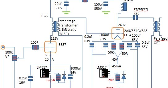
Fascinating. I wonder if the the output transformer inductance and impedance has factors in this including inductive elements of the tube. This is looking at it the ac analysis of the vacuum tube where the cathode is an inductor series the plate resistance with the grid being another inductor parallel to the cathode inductor to ground.That is also why I've mentioned (a lot) a mathematical concept called a 'cubic non-linearity'. SETs express a quadratic non-linearity. A cubic function allows the succeeding harmonics to fall off at a faster rate. So you just don't get the series that Keith showed.
If you could get an SET to express a cubic non-linearity instead of quadratic, it would sound better and be lower distortion/more transparent. That is why I said that the cubic exponent produces a superior harmonic decay series. I've been experimenting with that for several years now.
Because I've observed lower distortion when I change the SET transformer to a higher DC resistance (and impedance) distortion is lowered. Also, If I stick a low value Anton-perry resistor in the cathode circuit, that lowers the stay inductance in the cathode also lowers distortion. The SET transformer type in question I used was a gaped plate type.
Parafeed type circuits seem to have a different distortion and I imagine its because of the series capacitor of the SET transformer.
Using which exponent? This is a math thing.Howard did apply exponential decay.
From a simple google search: An exponential function is defined by the formula f(x) = ax, where the input variable x occurs as an exponent.
Choose a different exponent and you get different results! A fully differential amp uses a different exponent (based on a cubic function) and if you used the quadratic function, the results are irrelevant. That is why I say Howard's paper is a red herring- its interesting but doesn't apply to a fully differential amplifier so its just a theoretical thing; in the end Its a red herring.
The inductance of the elements of any tube are quite small so the inductance of the output transformer totally dominates.Fascinating. I wonder if the the output transformer inductance and impedance has factors in this including inductive elements of the tube. This is looking at it the ac analysis of the vacuum tube where the cathode is an inductor series the plate resistance with the grid being another inductor parallel to the cathode inductor to ground.
Because I've observed lower distortion when I change the SET transformer to a higher DC resistance (and impedance) distortion is lowered. Also, If I stick a low value Anton-perry resistor in the cathode circuit, that lowers the stay inductance in the cathode also lowers distortion. The SET transformer type in question I used was a gaped plate type.
Parafeed type circuits seem to have a different distortion and I imagine its because of the series capacitor of the SET transformer.
Its the topology of the circuit (for example, single-ended vs fully differential, or single-ended input with a PP output) that determines what the open loop distortion signature (i.e.: its distortion series; how fast the higher harmonics fall off as their order is increased) of the amp will look like, assuming the components, power supply, layout and grounding aren't a factor in a real execution.
In tube amps you also have the tube type and operating point that affect the distortion. For example, there is over a 10:1 difference in the distortion a 6SN7 makes depending on the design of the structure of the plate and grid from brand to brand, and we hear that difference quite easily. But the actual inductance of the devices is a small variable since there are much larger influences in any circuit.
Parafeed prevents DC current from the core of the transformer so its saturation character is completely different. But you have a resonance issue introduced as well as that coloration of the capacitor itself. So you solve one problem while introducing another.
He uses a linear function in dB; however, dB is a logarithmic function. This means it is not linear in terms of % THD.Using which exponent? This is a math thing.
From a simple google search: An exponential function is defined by the formula f(x) = ax, where the input variable x occurs as an exponent.
Choose a different exponent and you get different results! A fully differential amp uses a different exponent (based on a cubic function) and if you used the quadratic function, the results are irrelevant. That is why I say Howard's paper is a red herring- its interesting but doesn't apply to a fully differential amplifier so its just a theoretical thing; in the end Its a red herring.
Your amp, based on the measurements from Soundstage, shows that it doesn't follow anything like an exponential curve. The 2nd is lower than 3rd, 4th is lower than 5th, above that only odd harmonics are above the noise floor. That is no function at all!
Last edited:
a nice article about parafeed, its advantages and disadvantages. Who will say a, need to say b as well. parafeed with plate choke you get a dead silent se amp. Considering that these amplifiers are usually combined with highly efficient speakers, this is a fact that cannot be ignored.
 jandkaudiodesign.blogspot.com
Parafeed Output Transformer
Parafeed Output Transformer, Parafeed, Parafeed Single Ended Amplifier
jandkaudiodesign.blogspot.com
I think that Atmasphere does not have common sense, but the desire to be the last to speak. Even when it's a set of words, which is almost all posts.He uses a linear function in dB; however, dB is a logarithmic function. This means it is not linear in terms of % THD.
Your amp, based on the measurements from Soundstage, shows that it does follow anything like an exponential curve. The 2nd is lower than 3rd, 4th is lower than 5th, above that only odd harmonics are above the noise floor. That is no function at all!
He uses a linear function in dB; however, dB is a logarithmic function. This means it is not linear in terms of % THD.
Your amp, based on the measurements from Soundstage, shows that it does follow anything like an exponential curve. The 2nd is lower than 3rd, 4th is lower than 5th, above that only odd harmonics are above the noise floor. That is no function at all!
 If they had a facepalm emoji I'd use that.
 So it doesn't matter to you when I say that Soundstage grounded a speaker terminal, so got incorrect results?
How that can happen is if you apply a sine wave from a signal generator, and that signal generator is grounded by its AC cord, and then you connect a distortion analyzer at the output which is also grounded, unless you take care using a differential probe or isolation transformer, as soon as you connect the analyzer, one speaker terminal will be at ground. I explained what happens earlier.
Do you not read what I write or do you choose to ignore it?
The requirements for the anode choke are at the level of the requirements for the output transformer for the CE amp. Add a quality capacitor with a large capacity and an output transformer that is a bit simpler than usual due to the lack of clearance. This has nothing to do with hum, but it costs more.a nice article about parafeed, its advantages and disadvantages. Who will say a, need to say b as well. parafeed with plate choke you get a dead silent se amp. Considering that these amplifiers are usually combined with highly efficient speakers, this is a fact that cannot be ignored.
Connecting one end of the secondary winding of the output transformer to ground is necessary for safety, especially in amplifiers with high anode voltage, as in tubes 211, 845, ??70, especially 833?. This does not increase distortion, but reduces the maximum operating frequency.
For example, in my 6?33? monoblocks, the maximum operating frequency without grounding was 57 kHz, and after grounding it was 55 kHz. We thought that this was the rule, but after a number of experiments with the design of the output transformer, grounding made the transformer's hob better: the frequency becomes 60 kHz.
The sound has also become better, according to my feelings.
Similar threads
- Replies
- 0
- Views
- 162
- Replies
- 3
- Views
- 576
- Replies
- 24
- Views
- 3K
| Steve Williams Site Founder | Site Owner | Administrator | Ron Resnick Site Owner | Administrator | Julian (The Fixer) Website Build | Marketing Managersing |