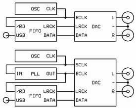
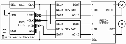
You can buy and install a so-called femto-clock but the clock signal that reaches the DAC chips is more likely a pico- or a nano-clock. The reason is the intervening logic gates used to select and divide the oscillator’s output to provide different bit- and word-clock rates as required.
Thirty years ago, I worked for a startup in the mainframe business. I was one of only a few programmers there and I was surrounded by dozens of the best digital hardware engineers in the business. The most often heard topics of conversation in the hallways and conference rooms pertained to clock distribution and signal integrity. Clocks were treated with great respect because the slightest perturbation would jeopardize the entire system. The chief engineer was fond of riddles. I remember one that asks, "When is a clock not a clock? … When it passes through combinatorial logic."
Blizzard proposes reclocking as a cure for all that ails USB audio. At the heart of any reclocking scheme is a latch. In its simplest form a latch is logic gate with two inputs, clock and data, and one output, data. It is used to capture the state of the input data at the instant the clock changes state, usually the rising edge. The output of a latch is data; not a clock.
Most USB DACs have two oscillators, one for sample rates that are multiples of 44.1K and the other for multiples of 48K. In most cases the oscillators are always running, each taking gulps of current from a common power supply and leaving behind a residue of their respective clock rates. The crème de la crème DACs use oven controlled oscillators (OCXO) because they are the most stable. However, OCXOs are always on and their output cannot be turned off. To select which oscillator is used to clock the DAC chips the circuit uses a multiplexor (mux). In its simplest form a mux has three inputs, one selector, two data, and one output, data. The selector signal chooses which input data is passed to the output. Now, the two pristine OCXO ‘femto’ clocks are dumped onto the same silicon substrate and pass, side-by-side, through a common logic gate, the mux.
The comical part is when the selected ‘femto’ clock crosses a galvanic isolation barrier to enter the dragon’s den, as it were, where is mingles with the CPU that manages the USB bus protocol. There it is divided down and joined with the sample data and sent back across the galvanic barrier and then on to the DAC chips. It's hard to imagine a worse digital audio interface.


