Sanders Sound Systems - electrostatic

Angela

WBF Technical Expert
May 24, 2010
141
0
0
Conifer, Colorado
Thank you for that informative explanation. I guess the next question was set up by you Roger. What is the difference between active and passive crossovers? Did I hear you say you prefer a brick wall crossover between the woofer and stat panel? At your leisure of course.

not ignoring you, dude. . . busy with lots of orders right now. be in touch soon, promise.
 

Gregadd

WBF Founding Member
Apr 20, 2010
10,565
1,790
1,850
Metro DC
not ignoring you, dude. . . busy with lots of orders right now. be in touch soon, promise.

That's what we want. Manufacturers building thier product.
 

Angela

WBF Technical Expert
May 24, 2010
141
0
0
Conifer, Colorado
Thank you for that informative explanation. I guess the next question was set up by you Roger. What is the difference between active and passive crossovers? Did I hear you say you prefer a brick wall crossover between the woofer and stat panel? At your leisure of course.

OK, put your feet up, boys, here comes Roger's response:


There are many issues involving crossovers, but let me begin with your first question, "What is the difference between active and passive crossovers?" The engineering definition is that "active" electronics (crossovers or any other type of electronics) include amplifiers in their circuits while passive ones do not.

But when audiophiles use the term "active" with respect to crossovers, they usually mean "electronic" crossovers, which are low level and active compared to "passive" crossovers, which are high level and passive. Since this is all rather confusing, allow me to dig into crossover theory and design a bit, with their pros and cons, and it will all soon make sense.

By way of review, there is no speaker type that can reproduce all the frequencies in the audio bandwidth well. So crossovers must be used to split the audio frequencies into bands that can be reproduced well by the various types of drivers (usually woofers, midranges, and tweeters).

This is rather easy to do using passive components like capacitors and inductors. A capacitor inherently will roll off the bass into a tweeter at 6 dB/octave. An inductor inherently will roll off the highs into a woofer at 6 dB/octave. The circuit is very simple as you need only put a capacitor in series with the tweeter and an inductor in series with the woofer.

You may have heard about the number of "poles" in a crossover. A pole is the inherent 6 dB/octave roll off in capacitors and inductors. A single pole crossover would operate at 6 dB/octave. A two pole crossover would be 12 dB/octave, three poles would be 18 dB/octave, etc.

A simple, passive crossover is made of inductors and capacitors that are placed in the speaker cabinet along with the drivers. A single amplifier can be connected to the crossover and the crossover will then energize the various drivers in the speaker cabinet. This is simple, cheap, and easy, so that is what most manufacturers used at the start of the high fidelity industry -- and most continue to use these passive, high-level crossovers to this day.

This type of crossover is passive because its components have no ability to amplify or control the musical signal. It is "high level" because it handles the relatively high power (hundreds of watts), high voltages (up to several hundred volts), and currents (up to a few tens of amps) found at the output of an amplifier.

But passive crossovers have many problems and limitations. The major ones are poor precision, distortion, phase shift, the inability to produce steep crossover slopes, and no buffering. Let me address these in some detail.

It is important to understand that different types of drivers should not reproduce the same frequencies. No two drivers are identical or behave identically, so if multiple drivers are used to reproduce the same frequencies, there will be various distortions and errors introduced as the two drivers interact with each other at the shared frequencies.

This is particularly true when woofers and tweeters are combined. A woofer is extremely limited in its ability to produce high frequencies and will not sound at all the same as a tweeter at those same high frequencies. While operating a woofer at high frequencies only messes up the sound, operating a tweeter at low frequencies will destroy it. So it is very important to confine a woofer to the bass and a tweeter to the highs.

Audiophiles tend to think that the various drivers pretty much stop operating at the crossover point, which technically is defined as that frequency where the signal is 3 dB below the reference or baseline level. But this is not at all true. The output from a driver only starts to roll off at the crossover point. It continues to contribute a substantial amount of energy to the sound far beyond the crossover point.

The output of a driver needs to be at least 48 dB below the reference level before its output is low enough that it can be ignored. So crossover slopes are very important.

A capacitor or inductor inherently rolls off the sound at 6 dB/octave. Therefore, a driver that is driven by a single-pole, passive crossover will continue to operate and produce useful sound output for fully eight octaves above (or below) the crossover point before its output will have diminished by 48 dB.

To put this in proper perspective, let's examine the woofer's contribution to the sound if it has a crossover point of 1 KHz using a crossover with a 6 dB/octave slope. Since an octave is double the fundamental frequency, one octave above 1 KHz will be 2 KHz. The second octave will be at 4 KHz, the third will be at 8 KHz, the fourth octave will be at 16 KHz, the fifth octave will be at 32 KHz, etc.

So you can see in this case, that the woofer's output level will only be reduced by 18 dB at 8 KHz. This means that it will still be generating a lot of output at frequencies that should be produced only by the tweeter. Therefore, a single-pole, 6 dB/octave crossover is virtually useless at keeping the woofer out of the treble region. The woofer's sound will remain a major contributor to the highs and will degrade them significantly.

The reverse is true when you consider the tweeter. If the crossover is at 1 KHz, then a 6 dB/octave crossover will reduce the power to the tweeter by only 18 dB at 125 Hz. Since the energy in music is rising rapidly as you get into the bass frequencies, this 6 dB/octave crossover slope does not adequately protect the tweeter's delicate, lightweight, voice coil from being burned up by excessive power. So 6 dB/octave crossover slopes are simply unsatisfactory.

Loudspeaker manufacturers quickly learned that they needed to use steeper crossover slopes. To make a high level, passive crossover produce a 12 dB/octave slope, you need only add an inductor going to ground to the tweeter circuit and a capacitor going to ground in the woofer circuit.

Now you can see that using our earlier example of a speaker with a 1 KHz crossover point that the woofer's output will be down by 36 dB at 8 KHz and the tweeter's output will be down by 36 dB at 125 Hz. This is a vast improvement over a 6 dB/octave crossover, although there is still far too much overlap of shared frequencies from both drivers for ideal performance and the woofer still operates much too high for great sound.

It would be better to use much steeper crossover slopes. But making steeper slopes with passive inductors and capacitors becomes very difficult because the tolerance of the components is so poor that you can't get their poles to match precisely enough to work correctly. After all, most capacitors have a tolerance of +/- 20%, and it is common for large capacitors like those used in speaker crossovers to have tolerances of +/- 50%. Inductors have only slightly better tolerances.

The precision problem limits most passive crossovers to 12 dB/octave. It is possible to make passive crossovers with steeper slopes, but to do so requires hand selection and individual measurement of each component to select for adequately tight tolerances. This is a time-consuming process that costs a lot of money, so is rarely done.

The simple, common, 12 dB/octave crossover just described contains just 4 parts (2 inductors and 2 capacitors). But it has a major problem. It produces a filter type known as "Butterworth."

This means that its behavior at the crossover point is quite sharp and when both the high pass section (the tweeter) and the low pass section (the woofer) are combined, the power output at the crossover point is doubled. This produces an irregularity in the speaker's frequency response at the crossover point in the form of a bump of 3 dB. Obviously, this has adverse effects on the sound quality of the speaker and is unacceptable.

It is difficult to solve this frequency response problem by using equalization (which would be the best way to do so) because passive crossovers have no amplification with which you can produce equalization. So most manufacturers electrically invert the phase of one of the drivers.

This puts the drivers out of phase by 180 degrees and eliminates the frequency response problem. Of course, putting the drivers out of phase has adverse effects on the sound. But the adverse effects of phase are minimal in comparison to the adverse effects of a major frequency response error. So a compromise is reached where accurate phase is sacrificed for accurate frequency response.

This problem with Butterworth filters is serious and was eventually addressed by Linquitz and Riley when they jointly developed the Linquitz/Riley filter. Crossovers made to the L/R specification have flat frequency response through the crossover point and therefore, the drivers could be left in phase.

But the L/R filter was about twice as complex as a Butterworth filter, so this increased the cost of passive crossovers significantly. Still, manufacturers of quality loudspeakers adopted the L/R filter type in the interest of better performance while manufacturers of cheaper speakers continued to use Butterworth filters and suffered phase anomalies.

There are other filter types that have been developed for crossovers by Bessel and Chebyshev. I won't get into the details of these as they are rarely used and difficult to implement in passive crossovers. But for those who want special characteristics, these special filters can be incorporated into electronic crossovers.

Note that phase anomalies are most obvious when they occur in the critical midrange region. So manufacturers of quality speakers worked hard to push the crossover points out of the midrange.
Since conventional, magnetic, 2-way speaker systems usually must be crossed over at around 2 KHz, they are very bad about having crossover anomalies in the midrange. Also, it is hard to get a wide enough frequency band out of magnetic drivers to make truly high performance, 2-way systems.

So most quality magnetic speaker systems have 3 drivers (woofer, midrange, and tweeter). This allows them to move the woofer crossover frequency down to perhaps 500 Hz and the tweeter's crossover up to around 5 KHz. This really helps eliminate the problems of crossovers in the midrange, although it doesn't completely solve the problems. Having three drivers with relatively shallow crossover slopes means that at most of the midrange frequencies, you will have all three drivers contributing significant sound, which is one of the reasons that the midrange quality of magnetic speaker systems is inferior to the purity of an ESL.

A 3-way system considerably complicates the crossover. You now need 50% more parts. If those parts are used in a L/R filter, you may need twice that amount. So quality speakers end up using rather complex and expensive passive crossovers.

Passive crossovers degrade the sound by inserting parts (capacitors, resistors, and inductors) between the amplifier and the drivers. Particularly troubling are inductors. These consist of a long (many feet) of thin magnet wire wound in the shape of a coil. As a result, an inductor has significant resistance. When you put resistance between an amplifier and its woofer, you ruin the electrical damping that the amplifier could apply to the woofer to help control the woofer and stop overshoot and ringing.

As if the resistance in inductors weren't bad enough, there are often resistors in the signal path too. These are required to give you some ability to adjust the levels of the various drivers to get them to match reasonably well and get acceptable frequency response. But a resistor will ruin the amplifier's damping even worse than an inductor.

There are other problems in passive crossover involving inductors. The main one is hysteresis. Hysteresis is a problem whereby the output signal does not exactly match the input signal because there is non-linearity and phase error when producing magnetic induction in the core of the inductor.

Most inductors use iron cores to make them more smaller and more efficient. As current flows through the coil of wire in an inductor, it forms a magnetic field. This magnetic field is more powerful if it induces magnetism in an iron core.

But iron-core inductors produce a lot of distortion because they have very big hysteresis losses. To minimize this problem, most quality loudspeaker manufacturers eliminate the iron core and use air core inductors.

Due to their inefficiency, air core inductors must be much larger than iron core inductors. Longer wire must be used. More resistance is involved, which worsens amplifier damping, increases costs, and makes the crossover larger. Hysteresis losses are not totally eliminated in an air core inductor, but they are greatly reduced. But on balance, it is fair to say that inductors simply don't behave very well in audio circuits and are best avoided if possible.

Capacitors are also problematical. Large value capacitors are required, so electrolytic types are preferred because of their relatively small size compared to non-polarized caps (like polypropylene, polyester, mica, etc.).

But electrolytic capacitors have their conductors wound inside of them, so they also have a significant amount of inductance, which can alter the desired frequency response of the crossover. Therefore, non-polarized capacitors often are used in the very best speakers, even though these are expensive and take up a very large amount of room.

Passive crossovers cannot be buffered. This means that their behavior and frequency response can be influenced by the external application of inductance, capacitance, and resistance.

Where would these external factors come from? Mainly from speaker cables. Manufacturers of speaker cables know this so deliberately make their cables have various values of inductance, capacitance, and resistance to change the frequency response of speakers.

This is a real crap-shoot because they have no idea of how a particular cable will affect a particular speaker. Of course, the longer the cable, the more inductance, capacitance, and resistance it will have, so the more it will alter the frequency response of passive crossovers.

A speaker is significantly affected by room acoustics. So some cables may compensate for some of the room acoustics in pleasing ways and others may make the room interactions worse. It all depends on the speaker, the cable, the room, and the listener's taste in frequency response.

All these variables are is why there is so little agreement and so much controversy about which speaker cables are "best." Simply put, there is no "best" cable because all the variables involved prevent you from predicting the sound from a system with a particular cable.

I could go on to cover many other problems with passive crossovers. But the main point is simple -- passive crossovers have very serious flaws for which there are no good cures.

Speaker manufacturers know very well that the solution to all these problems are active, low-level, "electronic" crossovers. Such crossovers are actually small preamplifiers that have crossover filters built into them. Think of the "tone controls" that used to be available on preamps and receivers. These could be used to roll off the highs or lows just like crossovers do.

Electronic crossovers operate at low levels ("line level", which is about 1 volt and essentially no power). They operate on the signal from the preamp rather than being fed by an amplifier like passive, high-level crossovers.

The line-level preamp signal is split into the various frequency bands by the electronic crossover and each is then fed to an amplifier that energizes its respective driver directly. There are no inductors, capacitors, or resistors between the amplifier and its driver that would cause distortion, phase shift, or ruin the damping.

Electronic crossovers don't need to use inductors with all their problems as all the frequency filtering can be done with just tiny capacitors and resistors. These capacitors and resistors can be made to very high tolerance with resistors being accurate to better than 1% and capacitors to around 2%. So multi-pole filters can be used to get steeper crossover slopes.

Like any good preamp, electronic crossovers have input and output buffers. So they are immune to the effects of external inductance, capacitance, and resistance.

Complex filter types like Linquitz/Riley are easily and inexpensively incorporated into electronic crossovers. It is also quite easy to make the crossover infinitely adjustable in real time so that the listener can simply tweak the crossover points, slopes, gain, etc. as he wishes to get ideal sound and the flattest frequency response. This is impossible with passive crossovers.

The distortion in an electronic crossover is nearly immeasurable and is vastly lower than in any a passive crossover. The components in electronic crossovers are tiny and inexpensive, so electronic crossovers can be made at lower cost than quality passive crossovers. Since there is no large passive crossover that needs to be housed inside a speaker cabinet, electronic crossovers allow the speaker cabinet to be smaller.

Of course, nothing is perfect and electronic crossovers have their flaws. The main one is complexity and cost from the standpoint of the audiophile. This is because an electronic crossover system must be bi-amplified (for a 2-way system), or tri-amplified (for a 3-way speaker).

So the audiophile needs to buy two or more amplifiers to use with an electronic crossover. This is a major barrier for most audiophiles. But the improved performance is well worth it if you are looking for the best sound quality.

Analog electronic crossovers are still limited in their ability to produce steep crossover slopes. Although the tiny parts involved have much higher precision than the large parts in passive crossovers, they still are not precise enough to produce more than about four filter poles (24 dB/octave slopes). And while 24 dB/octave slopes are vastly better than the 12 dB/octave slopes typically found in passive crossovers, it would be nice to use steeper slopes if there were a good way to do so.

Recently, we have seen the development of digital signal processing. This makes it possible to eliminate the problems and limitation of capacitors, resistors, and inductors completely. The frequency response of the filters can be done entirely in the digital domain by computation. So digital electronic crossovers are not dependent on and limited by the behavior of special electronic parts.

Digital crossovers come with selectible crossover slopes and filter types. It is easy to use 48 dB/octave, Linquitz/Riley filters using digital crossovers, while this is virtually impossible using analog ones. These steep slopes make it possible to completely eliminate the contribution of each driver within 1 octave of the crossover point, thereby reducing the shared bandwidth to a minimum and greatly reducing the stress on the drivers.

Additionally, it is fair to say that all speakers need at least some equalization to produce the best sound. At a minimum this involves increasing the bass output below 50 Hz to compensate for radiation resistance losses that cause all woofers to roll off below 50 Hz.

Digital electronic crossovers include equalization facilities using their built-in, digital signal processor. The amount and type of equalization varies from shelving equalizers (to compensate for speaker limitations) to full-on room correction systems with parametric equalizers and built-in, real time analyzers.

Yet another advantage of digital crossovers is speaker time-alignment. You probably have noticed that some of the best speakers have their various drivers at different planes in their cabinet. This is so that they are different distances from you.

Placing the drivers in different planes is desirable because some drivers are "quicker" and their sound gets to you before others in the same cabinet. Usually the sound from the tweeter arrives before the woofer. If the sound from all drivers does not arrive simultaneously, the phase behavior of the speaker will be adversely affected -- particularly through that region where two or more drivers are reproducing the same frequencies.

Therefore, many manufacturers try to "time align" their speakers by mounting their drivers in different planes. Unfortunately, this is difficult to do with good cosmetic results and often it is impossible to mount them far enough apart to completely correct the problem.

A digital crossover solves this problem by introducing digital time delay into the early-arrival driver. You can connect a microphone to the crossover and it will automatically produce test tones that will allow it to measure the acoustical distance to each driver.

It will then take this information and automatically delay the early driver by the amount required so that all the sounds from all the drivers arrive at your ears simultaneously. The digital crossover will even compensate for temperature differences in the room that alter the speed of sound! The result will be perfect time-alignment even in speakers (most of them) where the drivers are not in the optimum planes.

At this point, you should be gaining an appreciation of why I insist that no speaker can claim to be of truly high performance if it uses passive, high-level crossovers. The performance available from electronic crossovers (particularly digital crossovers) and multi-amping is simply far better. All speakers can be made to perform better using electronic crossovers than when using passive ones.

Now I would like to address a couple of common misconceptions regarding crossovers. The first is phase. Many audiophiles try to avoid steep crossover slopes in the belief that steep slopes cause more phase shift that degrades the sound.

While it is true that the steeper the slope, the more the phase is shifted, this is not what causes the audible phase problems in crossovers. The true cause of the phase errors that can be heard is due to the unbuffered behavior of passive crossovers. Let me explain.

I previously mentioned that because passive crossovers cannot be buffered, their frequency response can be altered by the external application of inductance, capacitance, and resistance. I stated that speaker cables were a major cause of this, which is true.

But I did not mention that passive crossovers will also have their frequency response altered by their drivers -- none of which have perfectly uniform impedance. Since the performance of a passive crossover can only be produced into a specific impedance, the expected frequency response of a passive crossover will not be perfect because the impedance of the drivers varies.

Now anytime that there is a change in frequency response, there will be a corresponding change in phase response. Look at the impedance of any speaker system with a passive crossover and you will see that it looks like a cross section of the Andes mountains.

The phase is therefore similarly altered. It is these ragged phase errors that exist across the music spectrum in passive crossover speakers that cause the adverse phase effects you hear from passive crossovers.

Note carefully that an electronic crossover is not affected by the impedance of the speaker. The speaker is driven by an amplifier, not the crossover. The frequency response of any well-designed amplifier will not be affected by the impedance of its driver. So there will be no ragged phase errors to be heard in an electronic crossover.

But what about the smooth even phase shift caused by the crossover slope? Doesn't that affect the sound too?

Actually, careful testing shows that human hearing is not very sensitive to a smooth, linear, sloping phase shift. So the effects of the phase shift caused by the crossover slope are virtually inaudible. In any case, the smooth phase shift of the crossover slope is vastly less apparent than the phase shift caused by the impedance variations and subsequent phase anomalies in passive crossover systems.
It is also true that human hearing is only really sensitive to phase errors through the midrange frequencies. Phase errors are inaudible at bass frequencies, and quite difficult to detect in the treble. So if you can keep the crossover out of the midrange, and particularly if you can keep it below 500 Hz, the steepness of the crossover slopes becomes a non-issue.

But even if you are convinced that steeper crossover slopes produce audible phase error, you need to look at the big picture. There can be no doubt that using drivers beyond their frequency response capabilities (like using woofers in the midrange and highs) and having a lot of shared frequencies between multiple drivers that are at different distances to you, severely degrades the sound.

This degradation does far worse things to the sound than any smooth phase error can. So it is well worth trading a little smooth phase shift for the much better frequency response, tight control of the sound, and improved sound quality that you can get by using steep crossover slopes.

I am not willing to compromise the sound quality of my speakers. So I simply will not, and do not use passive crossovers. To assure that there is no adverse sound quality from the crossover, I use very low crossover points (172 Hz in the Model 10c and 220 Hz in the Model 11).

No matter how good a woofer is, it simply can't match the spectacular detail and clarity available from a single, massless ESL in the midrange. So I use 48 dB/octave slopes to assure that the woofer only operates in the bass. The ESL reproduces all the frequencies from the upper bass to beyond the treble as a single driver without any crossovers at all.

The ESL must not be operated at or near its fundamental resonance or the speaker will exhibit high Q behavior (overshoot and ringing), which sounds awful. By using very steep slopes, I am able to operate the ESL down to within an octave of this resonance without exciting it.

The equalization facilities of electronic crossovers allow me to compensate for the midrange phase cancellation inherent in all dipole radiators. This is a far better way to correct this frequency response error than by using multiple panels of different sizes and crossovers to operate them at different frequencies as is commonly done in many ESLs.

As a result of the use of electronic crossovers, particularly digital ones, the performance of my hybrid ESL is now better than a full-range, crossoverless ESL. This is because my ESL is operated nearly full range (172 Hz to 34 KHz), and yet it has a superb transmission line woofer that will produce prodigious amounts of deep bass, which a full-range ESL cannot hope to match.

In summary, electronic crossovers are essential if you want outstanding speaker performance. This is especially true of hybrid ESLs.

I hope this information, although limited in scope, has been helpful. If you have further questions, please feel free to contact me.

Great listening,
-Roger
 

kach22i

WBF Founding Member
Apr 21, 2010
1,592
210
1,635
Ann Arbor, Michigan
www.kachadoorian.com
FYI: Bronze at the Rock Mountain Show.................2008? Must be the older model, pre-TL.

While it's nigh impossible to choose ONE speaker that was "Best of All",

we've tried to identify those that stood out the most in terms of sound, price and appearance - in that order.

..........................Completely breaking the electrostatic limitations of not playing very loud or going very low, as well as being very hard to drive, Roger Sander's reasonably priced ($12,999) electrostat 10b will play all day at 100+db and go down flat to 20Hz with 98db efficiency. Integrating with the rugged Ultrastat panel is a 10" bass driver utilizing a magnetic damping system that starts and stops up to 10x faster than conventional drivers, Sanders says. It's installed in a proprietary transmission line controlled by its own included 600 watt Crossover Amplifier. An electronic crossover completes the system and offers finite adjustment of the bass and mid frequency balance to accommodate room variability and personal preference. Just add your own power for the stat panels.(He makes that, too if you need it)

Now if he could only increase that narrow sweet spot so those of us with wives that love to listen with us could hear both channels, too - without sitting directly in back of us. We are expecting these for their first review as well.


Surf'n around that same site brought this up:
http://www.stereomojo.com/Sanders 1...ew/Sanders10bElectrostacticSpeakersReview.htm


I see no date on the article, but I assume it to be 2008, so the TL goes back to that date and or before.
 
Last edited:

Angela

WBF Technical Expert
May 24, 2010
141
0
0
Conifer, Colorado
Good detective work, the review was done in June 2009 and it was the first speaker review on the 10 series. The TL has always been in Roger's speaker designs for all the reasons he has outlined. the first published article was about 20 years ago.

If you get a kick out of going back in time -> http://www.sanderssoundsystems.com/...b_1990_A_compact_integrated_esl-tl_Part_I.pdf

for the rest of Roger's articles, going back to 1976 (lawdy ) -> http://www.sanderssoundsystems.com/audio-related-articles


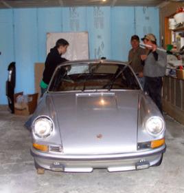
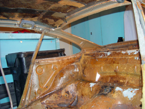
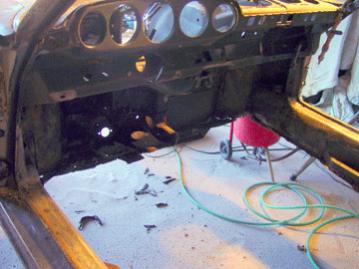
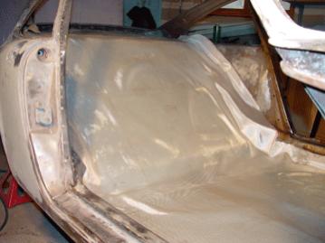
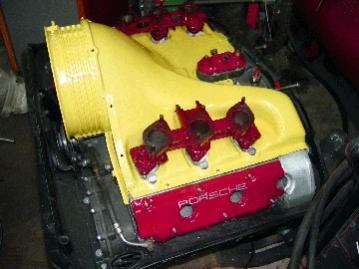
and by the way, George, one of Roger's daughters is an architect in SF and he is in the process of restoring from literally the ground up, a 1972 Porsche. small world, eh?

porsche1..jpg porsche2..jpg porsche3a..jpg porsche3..jpg porsche4..jpg

as it arrived, the kid in picture (on the left) is who Roger hired to do the tear down and get ready for paint work. This also gave an unemployed teen some work through the winter. It came from Detroit from a guy who bought it to restore it and race it, but never got around to it, so he towed it and the new racing engine that he had done for it out. lots of rust, Roger had the kid cut out the entire bottom of the car and replace it all with foam and fiberglass. Roger has taken off over 800 lbs of weight so far and continues to customize and machine parts as needed. the colors are yellow and maroon. almost ready for paint.
 
Last edited:

kach22i

WBF Founding Member
Apr 21, 2010
1,592
210
1,635
Ann Arbor, Michigan
www.kachadoorian.com
one of Roger's daughters is an architect in SF......restoring....a 1972 Porsche...... Detroit.
Bad time to be an architect in Michigan (SF not much better from what my cousin tells me) , here over 75% are out of work, offices closing left and right. I'm in the process of diversifying my business to include Industrial Design and Production Design (storyboards, stage design etc...) work.

The metro Detroit Craig's list was the place to look for Porsche's this winter. Typically you would only find about ten cars, most of them 944's. This winter 100's of Porsches for sale, most bargains and lots of 911's too.

The 1972 sounds like it will be a nice car, I own a 1977 911 Targa with some spot rust. I don't understand the floor board part, being a unibody welded in steel is typical. A good resource for forum help is Pelican Parts. They have talked me though things I would have never tried on my own, and working well outside my normal comfort zone.
 

Gregadd

WBF Founding Member
Apr 20, 2010
10,565
1,790
1,850
Metro DC
Bad time to be over fifty and in any high paying profession.
Thank you for all your responses. They have been very informative and challenge some of my preconceived ideas.

I have advocates that the back wave of such a large dipole be killed or attenuated. Is your speaker radiating a back wave? What problems if any does this present for your speaker and dipoles in general.?Should we just leave it alone, buy absorption material or just move it away from wall?
 

Angela

WBF Technical Expert
May 24, 2010
141
0
0
Conifer, Colorado
Bad time to be over fifty and in any high paying profession.
Thank you for all your responses. They have been very informative and challenge some of my preconceived ideas.

I have advocates that the back wave of such a large dipole be killed or attenuated. Is your speaker radiating a back wave? What problems if any does this present for your speaker and dipoles in general.?Should we just leave it alone, buy absorption material or just move it away from wall?

You may attenuate the back wave of a dipole if you wish. But I generally do not consider this necessary or desirable. Let me explain the situation and you can draw your own conclusions.

The problem is that the rear wave from a dipole is just as powerful as the front wave. If this bounces off a nearby wall and comes back through the speaker, the frequency response will be ruined.


The reason for this is that the rear wave of the dipole that is reflected off the back wall will be slightly delayed compared to the front wave. So when the rear wave bounces back through the speaker, it mixes with the front wave and the its energy at each frequency will be either subtracted from or added to the energy from the front wave -- it all depends on the phase angle of the rear wave.


For example, let's assume that the timing (phasing) is such that at 1 KHz the rear wave phase angle is 180 degrees. This means that the rear wave will cancel the front wave and you will hear essentially no output at that frequency.


At 2 KHz, the phase angle will be 360 degrees, so the output at that frequency will be doubled (3 dB greater than the front wave alone). These are the extremes. Other frequencies will be at different phase angles that will either augment or depress the output by varying amounts.


The result of this type of strong reflection will be that the frequency response of the speaker will consist of a series of peaks and dips in the frequency response that resemble the teeth of a comb. So this type of problem is often referred to as a "comb filter." Needless to say, a comb filter sounds perfectly awful and must be avoided.


This problem can only occur if the rear wave bounces off the back wall and then comes back through the speaker where it can mix with the front wave.
This means that the speaker needs to be at least close to parallel to the wall. It won't be a problem if the angle of the speaker to the wall is significantly off parallel as any significant angle will result in the rear wave being bounced AWAY from the speaker. When this is the situation, a comb filter will not occur.

Of course, if the diaphragm is curved, the problem will occur over a much wider speaker angle than if the panel is planar. And note that regardless of the speaker's angle, the further away from the wall, the less likely that the reflected rear wave will hit the speaker on its first bounce. This is why moving the speaker further away from the wall usually helps the situation.


In the case of my speakers, they must be toed inward so that they face the listener. As a result, they are at a rather severe angle to the wall. This bounces the rear wave away from the speaker so that no comb filter will occur. So it is not necessary to place damping behind my speakers to correct the comb filter problem. The angle is sufficient that you can put my speakers directly against the wall and there still will be no comb filter formed.


Placing damping on the wall behind a dipole has a disadvantage. The rear wave will bounce around the room and add high frequency energy to the off-axis sound. So for casual listening when you are not at the sweet spot, dipoles will sound better if you don't absorb their rear wave.


Also, keep in mind that damping materials work best at the higher frequencies. As you get down into the mid-range, they won't absorb all the sound, so you usually will still get a comb filter in the mid-range frequencies, even if you try to absorb the rear wave.


This frequency-dependent behavior of damping materials also means that absorbing the rear wave will result in the rear wave mid-range frequencies escaping into the room while the highs are essentially totally absorbed.

The result will be a relatively mid-range-heavy sound with loss of highs when you casually listen out of the sweet spot.

So I generally do not recommend absorbing the rear radiation of a dipole.

It works better to toe the speaker inward so that it reflects the rear wave away from the speaker to eliminate the comb filter.

There is one exception to this recommendation, and that is if your room is very small. For example, when my speakers are used in recording booths, the rear wave energy bounces around in the tiny room and very quickly reaches the sweet spot, which can adversely affect the sound.


In a large room, this is not a problem because the rear wave energy is so delayed and attenuated by the time it reaches the sweet spot that our ears ignore it. But in a very small room, this is not the case. So I recommend absorbing the rear wave in very small environments.


In summary, for typical listening environments, it is not necessary to absorb the rear wave from a dipole as long as the speaker is not placed near parallel with the rear wall. If it is, then you can probably solve the problem by moving the speaker further out from the wall.


You may absorb the rear wave if you prefer. But this is not effective at mid-range frequencies and tends to make casual listening sound rather dull.

So it is not my preference.

-Roger
 

MylesBAstor

Well-Known Member
Apr 20, 2010
11,238
81
1,725
New York City
Amen on your room damping comments. Many of us over the years played with the Sonex panels as well as construction our own panels based on the article that appeared in The Audio Amateur many, many moons ago-with rather ambigous results.

Thought we had gotten away finally from the LEDE room fiasco so popular it seems back in the 90s.

I totally agree with the problem of non-linear absorption too of the material. And what I have found in the past is that people are trying to roll off the upper octaves when the problem often is actually more in the upper midrange. So in the end, you still aren't happy with the solution!
 

Gregadd

WBF Founding Member
Apr 20, 2010
10,565
1,790
1,850
Metro DC
Well thank you for that important piece of information. It proves that common sense will only get you half -way there. And now for some controversy.
Tube vs. Transistor.You recommend solid state amplification for speakers. I can't dismiss solid state out of hand anymore. There are some excellent models out there. I also recognize the short comings of tube amps. At the price I am willing to pay. Hybrid seems the only way to go. Just can't imagine any solid state amp under $30k that I could live with. Ultimately it's the sound that matters. At least theoretically how do you support your choice of solid state over tubes?
 
Last edited:

czapp

New Member
Jun 14, 2010
2
0
0
Long Beach NY
www.carlzapp.com
I've had a pair of Innersound Kaya's for a little over 2 years now. Based on the recommendation of a certain room treatment manufacturer, I put some absortive panels on the wall behind the speakers. It was a disaster.
The stage became extremely shallow, and restricted to a small area in the middle of the speakers. Switching to diffusion panels brought it all back. I can also attest to Rogers comment that to increase the width of the stage, just move the speakers apart. I listen in the nearfield - about 7 feet from the panels, and there is over ten feet between them. Far and away the best soundstage I have had in my room. As for amplification, I am using what was once called the Innersound i-tube. It was originally designed by Terry Tekushan for Innersound, and he continues to make them. I had been through several solid state amps and was never happy. The i-tube is designed to deal with the impedence dips in the panels, and it handles them with ease. All other tube amps that I tried, regardless of power, were rolled off in the highs. The only other one that could handle the Kaya's was a David Berning OTL. That was an excellent combination.
Given the demise of Innersound, Roger has been an invaluable asset. He is one of the truly good guys in this business. Helpful, honest and responsive. I've never been happier with my system, (and I've been around that block many times), and knowing that Roger is there makes it a lot easier to sleep at night.
 
Last edited:

Gregadd

WBF Founding Member
Apr 20, 2010
10,565
1,790
1,850
Metro DC
Last edited:

Angela

WBF Technical Expert
May 24, 2010
141
0
0
Conifer, Colorado
Well thank you for that important piece of information. It proves that common sense will only get you half -way there. And now for some controversy.
Tube vs. Transistor.You recommend solid state amplification for speakers. I can't dismiss solid state out of hand anymore. There are some excellent models out there. I also recognize the short comings of tube amps. At the price I am willing to pay. Hybrid seems the only way to go. Just can't imagine any solid state amp under $30k that I could live with. Ultimately it's the sound that matters. At least theoretically how do you support your choice of solid state over tubes?

Here ya go, another chapter from The Rogernator:

I certainly agree with you that there is a lot of controversy surrounding tubes vs. transistors. But since you asked, I'll explain why I recommend solid state amps for driving my ESLs.

To do so, I must first give you some history and discuss some technical issues in what I hope will be understandable. I have designed and built tube amps going all the way back into the 60's. My most memorable design was a Class A, high voltage, transformerless output, direct-coupled tube amp for driving electrostats. I published the design in "The Audio Amateur" magazine back in 1976. You can still read it on my website at:
http://sanderssoundsystems.com/downloads/TheAudioAmateur0May1976.pdf

I have also used many other tube amps over the years and have also helped design the iTube, which was a conventional tube amp that was optimized to drive ESLs. The point I'm trying to make is that I don't have any bias towards one or the other type of device. I've used, designed, built, and marketed both types. So what I am about to say does not come from any particular partisan point of view. It is simply what I have learned over the last 38 years of research into producing the best sound I could.

I have been in the unusual position (for an audiophile) of having a fully-equipped test bench, including a spectrum analyzer. This has made it possible for me to carefully do both measurements and listening tests to correlate the two and to find out the reasons we hear the things we do. This research has been fascinating and very educational. It has also made it possible for me to develop truly high-performance electronics.

There is no doubt that we all hear differences between tube and transistor amplifiers. The big question is what is causing the differences we hear between them. After all, well-designed examples of both types measure well enough that we should not hear any differences between them. So what gives?

I spent a lot of time looking for the reasons. It was an extremely interesting and entertaining search. I don't have time to explain all the work I did over the years in these studies this message, but will be happy to discuss them over the phone (303 838 8130) if any reader wants to know. I'll just have to summarize here.

To begin, you need to understand how much power is required to play musical peaks cleanly and without clipping an amplifier. It takes a surprising amount.

To see what is going on with an amp when playing music only requires an oscilloscope. These are very fast (the slowest ones will show 20 MHz) and will clearly show amplifier peak clipping when music is playing. A meter is too slow to do so. A 'scope is cheap (you can get them for $100 on eBay all day long). So you don't have to take my word for what I am about to explain. Feel free to get your own 'scope and examine your system's performance.

You simply connect the 'scope across your speaker or amplifier terminals (which are electrically the same), adjust the horizontal sweep as slow as you can while still seeing a horizontal line on the screen. Don't go so slowly that you see a moving dot.

Now play dynamic music at the normally loud levels you enjoy. Adjust the vertical gain on the 'scope so that the trace stays on the screen.

As music plays, you will clearly see if clipping occurs. The trace (which will just be a jumble of squiggly lines) will appear to hit an invisible brick wall. It will appear as though somebody took a pair of scissors and clipped off the top of the trace. That's where the term "clipping" comes from.

If you see clipping at the levels you like to listen, then you are not using a sufficiently powerful amplifier to play your music cleanly. Your system is compromised because your amplifier will have compressed dynamics, sound strained, lose its detail, and have high levels of distortion.

The 'scope will be calibrated so that you will know the voltage at which clipping occurs by observing the grid lines. If you know the voltage and the impedance of your speakers, you can easily calculate the power.

Power is the voltage squared, divided by the impedance. So if the 'scope measures 40 volts at clipping, and you are driving 8 ohm speakers, you know that 200 watts are being produced at clipping -- and this is insufficient power for your particular system because it is clipping.

You will find that conventional, direct-radiator (not horn-loaded), magnetic speaker systems of around 90 dB sensitivity, typically require around 500 watts/channel to avoid clipping. More power is needed in larger rooms or if you like to play your music more loudly than most.

The key point I'm trying to make is that audiophiles usually are using underpowered amplifiers and are therefore listening to clipping amplifiers most of the time. When an amplifier is clipping, it is behaving (and sounding) grossly differently than its measured performance would suggest. This is because we always measure amplifiers when they are operating within their design parameters -- never when clipping. A clipping amp has horrible performance, so attempting to measure it is a waste of time.

In other words, we usually listen to an amplifier when it is clipping and we measure it when it is not. This is why amplifiers sound so different than their measurements would imply. It is not that measurements are wrong, it is simply that we are listening and measuring different conditions.

It is essential to understand that when an amp is clipping, it will sound quite different than when it is not clipping. It is also important to realize that different types of output devices (tubes vs. transistors) clip in very different ways, so sound quite different when they are clipping.

Finally, it is important to realize that an amp does not instantly recover from clipping. It takes several milliseconds for its power supply voltage to recover, for it to recharge its power supply capacitors, and for its internal circuitry to settle down and operate properly again. Therefore, even though an amp may only be clipping on the musical peaks, it will not immediately operate properly at average music levels where it is not clipping.

It should now be obvious why objective measurements don't seem to give much insight into the performance of amplifiers. It is not that objective measurements aren't accurate (they are superb), but simply that we don't usually operate amplifiers within their design parameters. So we aren't listening to them at the power levels where they operate properly and where their measurements are meaningful.

Now let's analyze tube and transistor equipment with regards to clipping, since that is the condition to which we usually listen. There is "hard" and "soft" clipping. If you go back to the oscilloscope investigations, you will see that solid state amps clip "hard" in that there is an absolute, rock-solid, limit to how loudly they will play. As soon as you reach that point, they immediately clip. This point is their power supply rail voltage.

A tube amp clips "softly." This is because tubes produce a cloud of electrons around their cathodes.

This cloud has surplus electrons available so that for sudden current surges (such as musical peaks), a tube can deliver more current (electrons) and voltage for a few milliseconds before they clip. So their clipping threshold is not rigidly fixed as it is in a transistor amp. It varies depending on the dynamics of the music played.

The age of the tube matters a lot in this situation. As a tube ages, its emissions decrease and it cannot develop as many electrons in the cloud. So old tubes will tend to hard clip while new tubes will tend to soft clip.

Transistor amps usually must employ protective circuitry. Tubes do not need any. Protective circuitry will trigger anytime a transistor amp "sees" an excessive or dangerous load. Generally, this means that most transistor amps will trigger their protective circuitry at or about the time of clipping. They will also go into their protection modes at very low power levels if they see difficult loads (like electrostatic speakers).

Protective circuitry works by switching off the power to the output transistors for very brief periods of time. Well-designed protective circuitry will trigger on and off hundreds or even thousands of times per second to limit the power that the output transistors must handle.

Protective circuitry sounds awful. It literally puts gaps in the music, which adds a type of grainy quality to the sound. But more importantly, anytime you flip a switch, whether it is a light switch or an output transistor, you will get a voltage spike. So protective circuitry will replace a smooth musical signal with a chopped up one that has voltage spikes on each side of a gaps in the music. Is it any wonder that transistor amps sound harsh when clipping?

In addition, when a tube amp clips, it produces a lot of lower harmonics in its distortion profile. Low harmonics are relatively benign and don't sound too badly. But distortion is still distortion and these harmonics don't belong there. Also, just because a tube amp makes a lot of lower harmonics, doesn't mean that it doesn't also make higher harmonics, it does. And high harmonics tend to sound dissonant and unpleasant.

This is easily seen on a spectrum analyzer, which shows each harmonic and the percentage of distortion it adds to the sound. It truly is an amazing tool.

Transistor amps tend to produce a lot of high harmonics. This is actually due more to the operation of their protective circuitry and all the spikes it produces. So generally, transistor amps will have more of the unpleasant higher harmonics than do tube amps.

It is important to note that if a transistor amp does not have any protective circuitry, its distortion profile will be much more similar to a tube amp than to a transistor amp with protective circuitry. The effect of protective circuitry is a very critical issue in the sound of solid state amps and should be more widely recognized for the problems it introduces to the sound.

What all this boils down to is that clipping tube amps sound rather soft and smooth. Clipping solid state amps sound harsh and edgy. I think it is safe to say that we would all agree that if you must listen to a clipping amp, a clipping tube amp is more pleasant than a clipping solid state amp.

It should now be apparent from where "tube sound" and where "transistor sound" comes. It comes from the sound of clipping amplifiers, which do indeed sound quite different.

Of course, when clipping, neither amplifier sounds good. They both lose their dynamics, sound "mushy", lose their detail, sound strained, tend to sound harsh (particularly transistor amps), and are somewhat distorted.

Note carefully that human hearing is rather insensitive to transient distortion, so even though both amps will produce several tens of percent distortion when clipping, we generally won't recognize the distortion for what it is, because it is too brief. Instead we will perceive and describe the sound as "harsh", "strained", "fatiguing", "muddy", etc.

To have a truly high-fidelity music system therefore requires very powerful amplifiers. Amplifier power is the single most important factor in choosing an amp. Without adequate power, all amplifiers sound badly. You can pick a clipping amplifier based on it not sounding as badly as another amplifier (tubes usually preferred over transistors), but if you really want clean, dynamic, effortless, and smooth sound, you simply must use adequate amplifier power.

In short, my take on amplifiers is to use a tube amp that clips gracefully if I must listen to a clipping amp. But I'd rather have an amplifier with so much power that it never clips! The sound from powerful amps is dramatically better than underpowered amps, even if they clip nicely.

There are three quality criteria that a good amp must meet. It must have inaudible noise, it must have flat frequency response, and it must have distortion of less than 1%.

Interestingly, tests conclusively show that humans cannot hear distortion of less than 1%. So even though one amp may have 1% distortion and another 0.001% distortion, they will both sound identical to us.

My spectrum analyzer will show distortion down to around one ten thousandth of one percent (0.0001%). It shows amazing differences between properly operating amplifiers. But as long as those distortion levels are below 1%, the amps will not sound any different to us.

It should now be clear that tubes only sound significantly different than transistors when you are listening to clipping amps. If the amps aren't clipping, or if you are using a component that doesn't clip (like a preamp), you won't hear any significant difference between well-designed tube and transistor equipment. So a hybrid amp (tube front end and transistor output stage) that is not clipping will not sound any different than a pure tube or transistor amp. And if it is clipping, it will sound like a transistor amp, not a tube amp, because it is the type of output stage that determines the sound of a clipping amp.

Now with the historical and general information covered, I can now turn directly to your question. So let's examine tube and transistor amplifiers with respect to their performance with ESLs (because I am a manufacturer of ESLs).

Recall that the basic quality performance criteria requires that an amplifier have flat frequency response. This is a huge problem for tube amps due to impedance variations in the load. Let me explain.

One of the laws of physics states that the source impedance must be lower than the load impedance or the load will be starved for current. What this translates to is that the amplifier's output impedance must be lower than the speaker's input impedance or the frequency response will be rolled off in those areas where there is this impedance mismatch.

Tubes are inherently high impedance devices. A large power tube like a 6550 or KT-88 has an output impedance of around 2,000 ohms. By comparison, a large power transistor has an output impedance of less than one ohm.

Tubes cannot drive loudspeakers directly due to their high impedance. To correct this problem, output transformers are used in most tube amps. These transformers have a specific turns ratios that will convert the tube's impedance from several thousand ohms to typically 4, 8, or 16 ohms.

Therefore, if you use the 8 ohm taps on the amplifier's output transformer with an 8 ohm loudspeaker, there should be no impedance mismatch, the frequency response should be linear, and the amp should deliver its maximum power. Unfortunately, this is never the case because loudspeakers do not have a constant impedance across their full frequency bandwidth.

Look at the impedance curve of any conventional loudspeaker and you will see that it varies from slightly below its "nominal" impedance to around 50 ohms. This will cause the frequency response from a tube amp to have errors. This is also another reason why tube amps sound different from transistor amps.

This impedance problem is relatively minor when dealing with conventional, magnetic speakers. But an electrostatic speaker is an entirely different animal. An ESL is a capacitor, not a resistor like a magnetic speaker. The impedance of a capacitor is inversely proportional to frequency. Therefore the impedance of an ESL typically varies from around 150 ohms in the midrange to about 1 ohm at 20 KHz.

A tube amp will be able to drive the high impedance frequency bandwidth (the midrange and lower highs) of an ESL with linear frequency response. However, at higher frequencies, the impedance of the ESL will drop below the impedance of the amplifier and the amp will then roll off the highs to some degree depending on the exact impedance mismatch and the frequencies involved.

This impedance mismatch problem can be minimized with both types of speakers by using a lower impedance tap on the tube amp's output transformer. For example if you use the 4 ohm tap with 8 ohm speakers, you will probably not encounter any impedance mismatch, so the system would then have linear frequency response.

Using the 4 ohm tap with ESLs will help, although it will still not eliminate all the high frequency impedance mismatch because the speaker's high frequency impedance will fall below 4 ohms. But probably only the top octave or two will be affected, which is hard to hear so the roll off may not be noticed subjectively.

But there is a problem when you use a lower impedance tap -- the drive voltage drops. Or to put it another way, the amplifier's output voltage is directly proportional to its output impedance.

Understand that the power available from an amplifier is a function of its output voltage. Ohm's Law is very simple and states that, "One volt will drive one amp through one ohm." With this simple concept, you can calculate virtually anything having to do with electronics as you will soon see.

Voltage is the pressure used to push current through an electrical circuit. Current is the flow of electrons in the circuit -- like water flowing though a hose. Current is measured in amperes, commonly called "amps." Power is measured in watts and is the product of volts times amps.

Resistance is measured in ohms. The term "resistance" is used in DC (direct current) circuits. "Impedance" is the same thing as resistance. But it is used when discussing AC (alternating current) circuits because the impedance often varies with the frequency of the AC.

Since power is the product of volts times amps, you can see that you must get current to flow through the speaker's impedance. This requires volts.

For example, if you have an 8 ohm speaker, how many volts must the amplifier produce to push enough current through the speaker to produce 100 watts? How many amps of current will be flowing through the speaker at 100 watts?

There are simple calculations for determining this. The volts can be calculated by taking the square root of the power times the impedance. So for the example above, the watts are 100, multiplied by 8 ohms, gives you 800. The square root of 800 is 28.2 volts (RMS).

The current can be calculated in several ways, but the most common is take the square root of the power divided by the impedance. So in this case, the current flow would be 3.5 amps.

If you have a 100 watt amplifier, you can see that its output voltage will be limited to about 28 volts. If it could produce more voltage, it could produce more power, so you know that its voltage will be limited to 28 volts or it would have a higher power rating. Of course, all this assumes that the amplifier's power supply and output impedance is such that it can deliver the 3.5 amps needed to produce 100 watts of power.

You can also calculate that if an amp can produce 28 volts into 4 ohms (half the impedance of the above example), that the current would double to 7 amps and the power would double to about 200 watts. Hence you see transistor amps with power ratings listed for both 8 and 4 ohms.

Tube amps are different in that if you reduce the impedance of the transformer from 8 ohm to 4 ohms to match the impedance of the speaker, the output voltage will drop as a function of the turns ratio of the transformer, and so will the power.

The turns ratio is the square root of the primary impedance divided by the square root of the secondary impedance. This always works out such that the voltage will drop to the point where the amplifier will put out the same power at either impedance when driving a matching load.

When driving an ESL, voltage is everything. So when you drop the impedance of the output transformer, you reduce the output that the amplifier can produce from the ESL. In short, you have to trade output for more linear frequency response. This is a huge problem. It's a battle that you just can't win.

Note that OTL tube amps don't solve this problem. They have no transformer, so must relay on putting many output tubes in parallel to lower the impedance. This quickly results in having an absurd number of tubes with all their heat and power requirements. So OTL amps do not get down to very low impedances.

Most get to just around 10 ohms and the best only get a bit lower. As a result, they have severe impedance mismatch issues and are really quite a poor choice for driving ESLs. They also measure really poorly on a spectrum analyzer compared to transformer-coupled tube amps.

By comparison, powerful solid state amps typically have output impedances of around 0.02 ohms. They therefore have no trouble driving any speaker impedance with perfectly linear frequency response.

Solid state amps have high output voltages compared to tube amps. So they will drive ESLs quite loudly before clipping (unless they have protective circuitry that trips them up).

Well designed solid state amps have much lower distortion than tube amps. The best conventional tube amp I've ever measured was a McIntosh 275 with new tubes. It had only 0.3% distortion at an output level of 75 watts/channel (it clipped at 90 w/c). Most tube amps have distortion of somewhat more than 1%, even at levels well below clipping.

My specially designed iTube amp measured only 0.1% distortion in the midrange frequencies and went up to 1% by 20 KHz. It would do so at 150 w/c. But this was a special-built device and is not typical of conventional tube amps.

By comparison, most quality, solid state amps have distortion levels down around 0.002%. This is magnitudes better than tube amps. However, it is also true that humans cannot hear the reduced distortion levels in solid state amps, even though a spectrum analyzer will show dramatic differences between them.

Still, distortion is distortion. Why have any more than you must?

I think you can now see why I prefer very high power, solid state amps without any protective circuitry for driving ESLs. This is because they can drive ESLs with linear frequency response, while tube amps roll off the highs.

Solid state amps are much more powerful than tube amps and can supply vastly higher output voltages. As a result, a good solid state amp can drive my ESLs to ear-bleeding levels without clipping. And remember, it is clipping that produces "tube" or "transistor" sound. If a solid state amp does not clip, it does not sound harsh. It sounds just as clear and soft as a tube amp that is not clipping.

Transistor amps can run cool and efficient. My ESL amp runs only warm, yet can deliver the equivalent of about 1000 watts into an electrostatic speaker. No tube amp can do so, and even a relatively low power tube amp will run very hot and waste a lot of expensive electricity.

Tube amps are expensive compared to good solid state amps of similar power. Tube amps require expensive tube replacements, while a quality solid state amp is a no-maintenance, lifetime item.

Tube amps require biasing. Traditionally this had to be done by the audiophile on at least a monthly basis. This was a hassle and rarely was done, so most tube amps were always running far from their ideal performance levels.

Some tube amps tried to get around this biasing issue by using a "self-biasing" system. But this cut their power by about 30%. Some of today's latest tube amps use servo biasing systems, which are great if they work reliably. Often they don't.

Due to their high internal voltages and high temperatures, tube amps are unreliable. They often fail and have to be returned to the manufacturer for expensive repairs.

In short, tube amps can't drive ESLs linearly, cleanly, without clipping, to high output levels. So why put up with all their problems of heat, cost, maintenance, and unreliability when a properly-designed, solid state amp solves all these problems?

I therefore no longer design, manufacture, or recommend tube amps. I only build very powerful solid state amps that have no "transistor sound" because they do not clip or have any protective circuitry to ruin the sound.

Using my ESL amp on the panels of my speakers, and my Magtech amp on the woofers, results in approximately 1,400 watts of power for the speakers. This makes it possible to reproduce something like a grand piano or drum set at live levels in your listening room without clipping. You can reproduce a full symphony orchestra at Row A concert hall levels.

If you have a particularly large room or play your music at ear-bleeding levels, you can use the monoblock versions of my amps. The ESL amp will deliver more than 2,000 watts to the panels and the Magtech will deliver about 1,800 watts to the woofers. Clipping simply isn't an issue and the speaker can take the power.

This performance simply cannot be obtained using conventional tube equipment. So I really have no choice but to use and recommend excellent solid state amps.

I suspect that much of what I have just said is hard for you to believe or accept since you are obviously a "tube guy." I have no problem with that as clipping tube amps do sound better than clipping transistor amps, so I can appreciate that you prefer tubes.

I would be happy to send you one of my Magtech amps to compare to your tube equipment. I think you would be surprised at how good a high power, low distortion, voltage regulated, low impedance, solid state amp without any protective circuitry sounds -- and it is a reasonable price. I would send you an amp to demo at my expense (free round trip shipping). You can then draw your own conclusions and tell the forum what you discover.

Great listening,
-Roger
 

Gregadd

WBF Founding Member
Apr 20, 2010
10,565
1,790
1,850
Metro DC
Do you plan to show at the RMAF this year? Perhaps we can meet there? I have not decided whether to attend. Maybe if the good lord is willing and the creek don't rise.(or if I decide I like flying after going to California. Don't worry I plan to get the whole Sanders experience. The speaker that is. As everybody knows if you could pry my Moscode 402au from my hands you are the man.
 

Gregadd

WBF Founding Member
Apr 20, 2010
10,565
1,790
1,850
Metro DC
One more thing. In that you tube video I posted what tt/cart/arm combo is that.
 

Mobiusman

Well-Known Member
May 24, 2010
704
560
1,655
Jersey Shore- waterside
I believe that I heard this iteration of the Sanders at THE Show in 2009, but I am not sure that it is the same as what HP reviewed. However, I will say that what I heard impressed me greatly, as it did for Marty, although he was not quite as excited as I was. I have been a long-term electrostat fan because of the "nature" of their sound, even though I suspect that this "nature" is not necessarily the truest sound out there. Let me make my bias completely clear- I like this sound because it pleases me, not because it is necessarily the truest. Despite the fact that I owned a set of Wisdom M-75 Limited Edition References (hand picked for response), I must admit that I liked the stat personality better.

Given my bias, I found the Sanders to be among the best sounding stats and least obvious hybrids I have heard yet, and therefore liked them a lot. There is little doubt that they are highly directional and thus you must sit in the sweet spot to get the best results. Granted you can change the angles of the speakers or the size of equilateral triangle as HP says to change the image, but this is still a very socially unfriendly speaker due to a very small sweet spot.

Back in the days when I had an A grade system and room, my friends would joke that there should be a jig like one used for brain surgery in the "correct" position at the sweet spot. I even provided pillows to raise the head height of vertically challenged listeners. They were right and when you had your head in "the spot" magical things happened. Listening with my family was not one of them. When audiophiles came over, we took turns listening and when it was not our turn, we stood and observed the chosen one.

Maybe I am getting old, but this longer works for me. I like people more than my sound system. Yeah, I still choose the correct 3-4 seats in a 500-2000 seat theater when I go to a movie or concert because it is an event and usually there are two adjacent seats that qualify, thus allowing me to be happy in my selfishness for two hours. However, I live with my sound system and listen to music, watch TV and movies with it. I want it to disappear and I want ALL of my company to enjoy the experience.

Simple physics and acoustics clearly demonstrates that for a sound to sound real and thus believable (meaning my brain interprets it as real) the sound wave must START in a phase coherent manner, because that is the way sounds occur in the real world. Through triangulation and parallax of the signals obtained at your ears and eyes, your brain determines its position and you are satisfied that the sound is real and located at a specific position. When the sounds bounce off of environmental obstacles, your brain is able to use this information (phase alterations and time delays) to help understand the environment, thus maintaining the live aspects of the sound. The reason why I enjoy listening to my very phase coherent BG speakers on my deck after the sound winds its way through windows and sliders is because it started out initially extremely phase coherent and thus still sounds real as it emanates from my windows and doors, much like the voice of someone talking standing next to my speakers when I am hearing it from my deck. The difference is I believe that they and the music are in my living room and I am hearing it on my deck. Still quite pleasing since as a non-psychotic person, that was all I expected in the first place.

So unless you are lone listener with a system and environment with a vice-like sweet spot, regardless of how good these speakers are you have to determine your priorities versus other aspects of life.
 

Angela

WBF Technical Expert
May 24, 2010
141
0
0
Conifer, Colorado
Do you plan to show at the RMAF this year? Perhaps we can meet there? I have not decided whether to attend. Maybe if the good lord is willing and the creek don't rise.(or if I decide I like flying after going to California. Don't worry I plan to get the whole Sanders experience. The speaker that is. As everybody knows if you could pry my Moscode 402au from my hands you are the man.

see how our minds think alike? Here is Roger's response with an offer that I think is hard to refuse
woot..gif

Hi Greg,

Yes, I will be exhibiting at RMAF this year. It's a great show and close to home, so it's a no-brainer.


You are most welcome to meet me there. However, my room is usually packed with listeners and I have very little time to spend with each of them. I would like to have a chance to really meet with you and spend a little time.

So I recommend that we meet outside of RMAF if that can be worked into your schedule.

The best way to do this would be for you to meet at my facilities the day after RMAF. That way we can do some really good listening and have plenty of time. I could even pick you up at RMAF and bring you to my home. You could stay overnight in our guest bedroom and I could then take you back to the airport. In other words, I'm flexible. The only issue around RMAF is that I'll be busy doing set-up and take-down so you may have to be a bit patient with me.


Of course, you could visit anytime you are in Denver. You do not have to wait for RMAF.


As for your Moscode 402au amp, I do not feel any great need to "pry it from your hands." It is a quality amp with good specifications and reasonable amounts of power. So I'm sure it sounds lovely with your speakers.


That said, there are amps that might produce somewhat better performance from your system. The main issue is that your Moscode is only about 300 watts at 4 ohms, so no doubt it is clipping peaks when you are playing your music loudly. You really could use more power.


As I've suggested a couple of times, I'd be happy to send you one of my Magtech amps for you to test and hear (at no cost) and report your findings to your audiophile buddies. It will produce about 900 w/c into your 4 ohms speakers, so it won't clip on loud, dynamic music and I think you would notice an improvement in the quality of your sound at high levels. But at modest levels, your Moscode is just fine.


Great listening,

-Roger
 

Gregadd

WBF Founding Member
Apr 20, 2010
10,565
1,790
1,850
Metro DC
If I have not done it before let me issue the following disclaimer: I have no affiliation or financial interest in Sanderssound. My sole purpose is to provide some insight into what I believe to be reasonably priced products that produce exceptional sound quality. Also I admire anyone who challenges established principles.
 

About us

  • What’s Best Forum is THE forum for high end audio, product reviews, advice and sharing experiences on the best of everything else. This is THE place where audiophiles and audio companies discuss vintage, contemporary and new audio products, music servers, music streamers, computer audio, digital-to-analog converters, turntables, phono stages, cartridges, reel-to-reel tape machines, speakers, headphones and tube and solid-state amplification. Founded in 2010 What’s Best Forum invites intelligent and courteous people of all interests and backgrounds to describe and discuss the best of everything. From beginners to life-long hobbyists to industry professionals, we enjoy learning about new things and meeting new people, and participating in spirited debates.

Quick Navigation

User Menu

Steve Williams
Site Founder | Site Owner | Administrator
Ron Resnick
Site Co-Owner | Administrator
Julian (The Fixer)
Website Build | Marketing Managersing