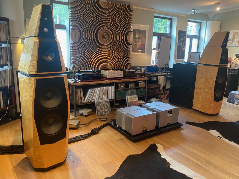
Back in the late 90's Goodwins High End had a pair in their big room which sounded incredible. System was all Spectral with MIT cabling. If I had a pair of these and was having trouble getting them to sing that's what I'd fall back on (or I'd just drive over to GHE and ask Alan Goodwin).they turn out to be a total nightmare to get playing properly.
Avalon Osiris , my next project!
- Thread starter shakti
- Start date
You are using an out of date browser. It may not display this or other websites correctly.
You should upgrade or use an alternative browser.
You should upgrade or use an alternative browser.
To my knowledge the MIT 850 speaker cables were developed in conjunction with the huge external cross overs of the Avalon Osiris project. The Osiris has 5 speaker cable inputs. I am using 2 sets of the MIT 850 cables, one set in TriWiring and one set in BiWiring. The best sounding interconnects are MIT as well. MIT 350 evo RCA is currently in use.System was all Spectral with MIT cabling.
I tried Spectral DMA 350 mono, but did preferred the JRDG 825 (later in BiAmping) with the Osiris.
The Audionet Heisenberg is the best Amp I had the chance to try so far.
High Power, strong damping factor, still sound with a flow.
The amplifier journey from
2x Jeff Rowland 825 in BiAmping
to
Audionet Heisenberg
and
Classe Audio Omega
made the obvious even clearer, the Avalon OsIris needs power!
But it seems, that the right damping factor might become similar important.
Too much made the bass deeper and more controlled , but the speakers were getting in a way slower and and less lively.
Than I became aware about the active damping factor control, Accustic Arts is offering in their amplifiers. Fortunately I had the chance to listen to a friends pair of
Accustic Arts MONO V
amplifiers and I was surprised about the performance, the Avalon Osiris was presenting.
( so I bought this amplifiers)
The speakers never played with such an easy and attac plus a very high resolution without changIng their natural tonal balance.
I cannot judge, if the big performance jump is related to the pure power of 2x900w/8ohm or because the active damping control makes this difference.
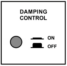
Switching the damping control on makes the speakers better balanced, as the damping factor is flattened over the frequency band. Switching it off will give the traditional maximum in lower frequencies and the Avalon was loosing some of the flow and ease specially in the midrange area.
It makes me smile, that even after 3 year the Avalon Osiris is still growing in performance , so I am looking forward to the next components to pass by for a visit .

The amplifier journey from
2x Jeff Rowland 825 in BiAmping
to
Audionet Heisenberg
and
Classe Audio Omega
made the obvious even clearer, the Avalon OsIris needs power!
But it seems, that the right damping factor might become similar important.
Too much made the bass deeper and more controlled , but the speakers were getting in a way slower and and less lively.
Than I became aware about the active damping factor control, Accustic Arts is offering in their amplifiers. Fortunately I had the chance to listen to a friends pair of
Accustic Arts MONO V
amplifiers and I was surprised about the performance, the Avalon Osiris was presenting.
( so I bought this amplifiers)
The speakers never played with such an easy and attac plus a very high resolution without changIng their natural tonal balance.
I cannot judge, if the big performance jump is related to the pure power of 2x900w/8ohm or because the active damping control makes this difference.
Switching the damping control on makes the speakers better balanced, as the damping factor is flattened over the frequency band. Switching it off will give the traditional maximum in lower frequencies and the Avalon was loosing some of the flow and ease specially in the midrange area.
It makes me smile, that even after 3 year the Avalon Osiris is still growing in performance , so I am looking forward to the next components to pass by for a visit .
View attachment 116006
Congratulations, Juergen!
Is the best sounding damping setting on high damping low damping?
Whaoo shakti…!!! Love your system! Looks amazing… Great to hear your new amps sounds so good. I’m happy for youThe amplifier journey from
2x Jeff Rowland 825 in BiAmping
to
Audionet Heisenberg
and
Classe Audio Omega
made the obvious even clearer, the Avalon OsIris needs power!
But it seems, that the right damping factor might become similar important.
Too much made the bass deeper and more controlled , but the speakers were getting in a way slower and and less lively.
Than I became aware about the active damping factor control, Accustic Arts is offering in their amplifiers. Fortunately I had the chance to listen to a friends pair of
Accustic Arts MONO V
amplifiers and I was surprised about the performance, the Avalon Osiris was presenting.
( so I bought this amplifiers)
The speakers never played with such an easy and attac plus a very high resolution without changIng their natural tonal balance.
I cannot judge, if the big performance jump is related to the pure power of 2x900w/8ohm or because the active damping control makes this difference.
Switching the damping control on makes the speakers better balanced, as the damping factor is flattened over the frequency band. Switching it off will give the traditional maximum in lower frequencies and the Avalon was loosing some of the flow and ease specially in the midrange area.
It makes me smile, that even after 3 year the Avalon Osiris is still growing in performance , so I am looking forward to the next components to pass by for a visit .
View attachment 116006
Have a great weekend !
/ Jk
the active damping control switch does not switch between high and low, it os more a switch between a max of damping factor in the low frequency range and a linearization of the damping factor over a wide frequency band.Congratulations, Juergen!
Is the best sounding damping setting on high damping low damping?
better described here:
4. 2. 1 General information
The damping factor D of a power amplifier is determined from the load resistance RL (connected loudspeaker, but for the measurement assessment 8 ? resistance) divided by the internal resistance of the amplifier Ri.
Physical equation: D = RL / Ri
D : damping factor (calculated number)
RL : load resistance (connected loudspeaker, for the measurement assessment 8 ? resistance) * Ri : internal resistance of the amplifier (usually measured at 1 kHz) **


7
Example: A power amplifier has (at 1 kHz) the internal resistance Ri =16 m?
The damping factor is then calculated to be 500. Physical equation: 8 ? / 0.016 ? = 500 *** This is a typical value for modern transistor power amplifiers.
(In comparison: at 1 kHz full tube power amplifiers usually have an internal resistance in the range of 0.4 ? to 4 ? and therefore a calculated damping factor in the range of 2 to 20)
Technical background:
* Loudspeakers do not have the same resistance at all frequencies. They are characterized by dynamic resistance, whereby the so-called complex load is formed by the spring mass system, deflection and movement speed of the membrane, induced counter-voltage in the voice coil, and crossover.
** The internal resistance of a power amplifier is also a dynamic variable. It is only valid for a certain working point, with a certain frequency and for a certain modulation. In addition, it can be determined in a number of ways.
*** These above-mentioned mathematical considerations do not take the loudspeaker cable resistance values or contact resistance (banana connector, cable lugs, etc.) into account. In reality these loudspeaker series resistance values and contact resistance values are naturally added to the internal resistance.
4. 2. 2 The technical part
As described above, due to the required high negative feedback reserve modern high power amplifiers with transistors have very low internal resistance (Ri) and therefore high damping factors. These high damping factors are desired because they have a very positive effect on important technical parameters, e.g. on distortion characteristics.
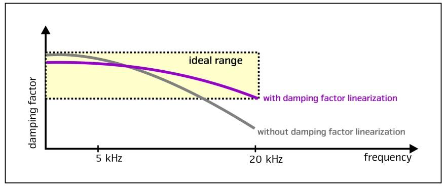
At 5 kHz the damping factor of a power amplifier is relatively linear and has a high value, but then for physical reasons (limitation of bandwidth) goes down with higher frequencies.
The degree and progress of the damping factor influence the in- and outswing behaviour and therefore the control of the connected loudspeaker by the power amplifier.
4. 2. 3 Claims and reality
Claims are often made that a higher damping factor is better for controlling the loudspeaker and therefore the system sounds better. This is not the case.
Correct is that a power amplifier with a very low damping factor is not able to sufficiently control the loudspeaker. It is, however, true that a loudspeaker does not have the best outswing behaviour with the maximum damping
factor.
The truth is that the value of the damping factor should in fact be within a certain range which is ideal for the loudspeaker and should also be linear for as long as possible over the frequency range.
4. 2. 4 Solution: damping factor linearization
In order to meet these two requirements (ideal range and linear curve), in the switch position "DAMPING FACTOR - ON" we lower the complete value of the damping factor slightly to the ideal value and then linearize it over a wide frequency range. In this process the advantageously high negative feedback reserves remain completely intact (see text above). If the push switch on the rear is not pressed, the function is not activated. The absolute damping factor is then maximized, but from 5 kHz decreases considerably. According to his preference, the customer can choose to activate the damping factor linearization or not.
8
Fig. 5: This simplified diagram serves to illustrate damping factor linearization

Yes, I had to sell some of my classic components to fund the new stuff in the houseHave you sold your Kenwood TT Jürgen ?
I have to say...I admire the remarkable way you have interwoven your equipment into a cohesive system...state of the art old and new. Not just all new 'references' that just came out, nor a trip down memory lane of yesteryear products (some good and some not as good as anyone actually remembers)...nor a wonderful collection which just seems more like a pack rat who cannot filter out what to keep and what not to.The amplifier journey from
2x Jeff Rowland 825 in BiAmping
to
Audionet Heisenberg
and
Classe Audio Omega
made the obvious even clearer, the Avalon OsIris needs power!
But it seems, that the right damping factor might become similar important.
Too much made the bass deeper and more controlled , but the speakers were getting in a way slower and and less lively.
Than I became aware about the active damping factor control, Accustic Arts is offering in their amplifiers. Fortunately I had the chance to listen to a friends pair of
Accustic Arts MONO V
amplifiers and I was surprised about the performance, the Avalon Osiris was presenting.
( so I bought this amplifiers)
The speakers never played with such an easy and attac plus a very high resolution without changIng their natural tonal balance.
I cannot judge, if the big performance jump is related to the pure power of 2x900w/8ohm or because the active damping control makes this difference.
Switching the damping control on makes the speakers better balanced, as the damping factor is flattened over the frequency band. Switching it off will give the traditional maximum in lower frequencies and the Avalon was loosing some of the flow and ease specially in the midrange area.
It makes me smile, that even after 3 year the Avalon Osiris is still growing in performance , so I am looking forward to the next components to pass by for a visit .
View attachment 116006
This must be quite a special system to hear, and the care with which you've selected and integrated each piece at a time has been fun to watch.
the active damping control switch does not switch between high and low, it os more a switch between a max of damping factor in the low frequency range and a linearization of the damping factor over a wide frequency band.
better described here:
4. 2. 1 General information
The damping factor D of a power amplifier is determined from the load resistance RL (connected loudspeaker, but for the measurement assessment 8 ? resistance) divided by the internal resistance of the amplifier Ri.
Physical equation: D = RL / Ri
D : damping factor (calculated number)
RL : load resistance (connected loudspeaker, for the measurement assessment 8 ? resistance) * Ri : internal resistance of the amplifier (usually measured at 1 kHz) **
View attachment 116016 View attachment 116020
View attachment 116017
7
Example: A power amplifier has (at 1 kHz) the internal resistance Ri =16 m?
The damping factor is then calculated to be 500. Physical equation: 8 ? / 0.016 ? = 500 *** This is a typical value for modern transistor power amplifiers.
(In comparison: at 1 kHz full tube power amplifiers usually have an internal resistance in the range of 0.4 ? to 4 ? and therefore a calculated damping factor in the range of 2 to 20)
Technical background:
* Loudspeakers do not have the same resistance at all frequencies. They are characterized by dynamic resistance, whereby the so-called complex load is formed by the spring mass system, deflection and movement speed of the membrane, induced counter-voltage in the voice coil, and crossover.
** The internal resistance of a power amplifier is also a dynamic variable. It is only valid for a certain working point, with a certain frequency and for a certain modulation. In addition, it can be determined in a number of ways.
*** These above-mentioned mathematical considerations do not take the loudspeaker cable resistance values or contact resistance (banana connector, cable lugs, etc.) into account. In reality these loudspeaker series resistance values and contact resistance values are naturally added to the internal resistance.
4. 2. 2 The technical part
As described above, due to the required high negative feedback reserve modern high power amplifiers with transistors have very low internal resistance (Ri) and therefore high damping factors. These high damping factors are desired because they have a very positive effect on important technical parameters, e.g. on distortion characteristics.
At 5 kHz the damping factor of a power amplifier is relatively linear and has a high value, but then for physical reasons (limitation of bandwidth) goes down with higher frequencies.
The degree and progress of the damping factor influence the in- and outswing behaviour and therefore the control of the connected loudspeaker by the power amplifier.
4. 2. 3 Claims and reality
Claims are often made that a higher damping factor is better for controlling the loudspeaker and therefore the system sounds better. This is not the case.
Correct is that a power amplifier with a very low damping factor is not able to sufficiently control the loudspeaker. It is, however, true that a loudspeaker does not have the best outswing behaviour with the maximum damping
factor.
The truth is that the value of the damping factor should in fact be within a certain range which is ideal for the loudspeaker and should also be linear for as long as possible over the frequency range.
4. 2. 4 Solution: damping factor linearization
In order to meet these two requirements (ideal range and linear curve), in the switch position "DAMPING FACTOR - ON" we lower the complete value of the damping factor slightly to the ideal value and then linearize it over a wide frequency range. In this process the advantageously high negative feedback reserves remain completely intact (see text above). If the push switch on the rear is not pressed, the function is not activated. The absolute damping factor is then maximized, but from 5 kHz decreases considerably. According to his preference, the customer can choose to activate the damping factor linearization or not.
View attachment 116019
View attachment 116018
8
Fig. 5: This simplified diagram serves to illustrate damping factor linearization
View attachment 116021
Which setting sounds the best ..!!!
Congrats on the new amps, as an Avalon Isis owner, those are absolutely stunning, hard to get over the finish on the Osiris. Beautiful.
- Buck
- Buck
Interesting...how do compare your Tidal Contriva G2s and the Isis?Congrats on the new amps, as an Avalon Isis owner, those are absolutely stunning, hard to get over the finish on the Osiris. Beautiful.
- Buck
Great question……was going to do a nice system thread here when I get a chance, I’ve been a long time reader but started contributing just recently……..so the Tidals are new, I’ve had the Isis for about 6 years and just recently spiked the Contrivas to get out of the “setup” phase. Several things, The Tidals seem to be cut from the same DNA, Accuton drivers (although made for Tidal of course), very holographic, excellent depth, way way more musical to my ear than some other typical hifi brands.Interesting...how do compare your Tidal Contriva G2s and the Isis?
The Isis really do sound great, but some major differences….first of all they absolutely dominate the room as they’re very large, the Contrivas make the roon much larger and seem to breathe left to right better. The diamond tweeter in the Tidals is far more resolving, smooth and accurate, the Isis has the first generation (I beleve) Accuton diamond tweeter and while excellent, has a bit of an edge, it’s not nearly as smooth and extended. Second, this may be more of a room thing but I get much much better and tighter bass with the Contrivas…..my lack of bass in my room with the Avalons has always been a bit of a mystery, but I have a large null in my room between 35 and 55 Hz with the Avalons which mostly disappeared with with the Contivas..…..who knows. Solo instruments such as piano, violin, classical guitar are to die for on the Tidals, the realism out paces the Isis by a fairly wide margin.
In general, the overall sound is similar yet the Tidals are far far more refined, resolivng and smoother without sounding the least bit artificial. They really are something.
- Buck
switched on the active damping linearizationWhich setting sounds the best ..!!!
Thank you! Very very interesting. Seems like similar DNA with superior execution. Excellent news! Enjoy and thanks for contributing to WBF! Look forward to reading more...Great question……was going to do a nice system thread here when I get a chance, I’ve been a long time reader but started contributing just recently……..so the Tidals are new, I’ve had the Isis for about 6 years and just recently spiked the Contrivas to get out of the “setup” phase. Several things, The Tidals seem to be cut from the same DNA, Accuton drivers (although made for Tidal of course), very holographic, excellent depth, way way more musical to my ear than some other typical hifi brands.
The Isis really do sound great, but some major differences….first of all they absolutely dominate the room as they’re very large, the Contrivas make the roon much larger and seem to breathe left to right better. The diamond tweeter in the Tidals is far more resolving, smooth and accurate, the Isis has the first generation (I beleve) Accuton diamond tweeter and while excellent, has a bit of an edge, it’s not nearly as smooth and extended. Second, this may be more of a room thing but I get much much better and tighter bass with the Contrivas…..my lack of bass in my room with the Avalons has always been a bit of a mystery, but I have a large null in my room between 35 and 55 Hz with the Avalons which mostly disappeared with with the Contivas..…..who knows. Solo instruments such as piano, violin, classical guitar are to die for on the Tidals, the realism out paces the Isis by a fairly wide margin.
In general, the overall sound is similar yet the Tidals are far far more refined, resolivng and smoother without sounding the least bit artificial. They really are something.
- Buck
Similar threads
- Replies
- 20
- Views
- 3K
- Replies
- 6
- Views
- 3K
| Steve Williams Site Founder | Site Owner | Administrator | Ron Resnick Site Owner | Administrator | Julian (The Fixer) Website Build | Marketing Managersing |

