I Believe in Power Cords

Gary,

Did you remember that this thread is about a Krell KSA250 humming transformer? Using this circuit with this amplifier can be very dangerous!
The currents involved, mainly at start up are very high, and an exploding 10000 microfarad capacitor can be a dangerous weapon. Also most electrolytic capacitors can not survive a longtime at 20 Amps current.

You're right. I forgot that. I was responding to speedskater and his single cap across the power line. This one is much safer, but wouldn't be able to pass 20 amps current.
 
Hi

Still makes the product does the 948. I would like however to understand the mechanism by which DC finds its ways after a transformer in the electrical distribution system. Or is it some kind of modulated DC riding above ground potential?

back to power cords..again if the AC is that bad, address it holistically from the electrical panel to the audio system.
 
You're right. I forgot that. I was responding to speedskater and his single cap across the power line. This one is much safer, but wouldn't be able to pass 20 amps current.

And one reason why they seem the size offered by either Isotek Syncro or Isol-8.
Cheers
Orb
 
IIRC, the main sources are leakage currents, often due to poor ground systems (from the pole all the way to your wall plug in the house), and as you surmised the impact of various components (not audio components, the fridge, etc.) that often run unbalanced with nasty power factors and their own isolation/leakage issues that can lead to unbalanced currents around the house. Motor start-up caps used to be one source.

I used to be a big fan of the Sola transformer line, not sure if they are still around. They made self-resonant transformers that were fairly pricey (relatively) but could be had from 100 W to 5 - 10 kW and would provide noise and transient surge filtering as well as isolation from the line. My main complaint with a lot of power conditioners today is they seem more marketing than real engineering, but it is not a research topic for me so I have not looked into them much.
 
You're right. I forgot that. I was responding to speedskater and his single cap across the power line. This one is much safer, but wouldn't be able to pass 20 amps current.

It was not about a cap across the AC power line!!!
It was a test bench set-up using a DC supply instead of the AC supply.
 
One point that is seldom touched on is that, all cables act as interference antennas. That includes: power, interconnect and speaker cables. In the case of power cables, they are both transmitting and receiving antennas! So with interference antennas, changing the cable length or construction style (twist or shield) or placement/routing, will change the effectiveness of the interference antenna.

It is worse because the mains circuits in the house are even larger antennas and transmitters, as researched by the BBC and shown how bad it is in the link I provided for the 6moons article.
TBH I feel the end cables are a bit of a smokescreen with their narrative on shielding for that purpose.
However technically it is possible that shielding can reduce some negative effects already being carried, but the downside is that many cables drain the shield to earth-ground and then affect technical-reference ground of the audio equipment plugged into.
Same way some conditioners shunt the noise from live-neutral to earth-ground and then themselves potentially aggravating behaviour of an audio equipment and its reference ground.

Cheers
Orb
 
Some major amplifier manufactures use DC blockers in their amps.
On another DIY forum, a thread documents almost 30 different blocker schematics (a few used by amp manufactures). With comments on the safety or effectiveness of several.
 
Makes sense to me. They are high-power, and the secondary is typically creating +/- HV rails from the primary, referenced to chassis (and hopefully on to earth) ground. Transformers work both ways, so unbalanced currents from the power supply could kick back into the AC line, and/or impact the safety ground and neutral current balance, creating an offset. How significant, how common, I have no idea.
 
Funny the other aspect I wanted to mention as food for thought was mains charging current for anything connected to the mains.
Even with THD of just 2.5% the difference when measuring current pulse is pretty noticable with the right gear, and depending upon the current draw as well.
As an example Keith Howard measured the P10 mains regenerator from the wall while the mains was suffering just 2.36% THD (another headache is how the THD figure can change due to real world interaction and a much earlier review-test with Isotek saw his mains with THD as high as 7%) and provided the following:
Without the P10 the current pulse was incorrect and capped at 3.5A over nearly 4 seconds, with the P10 it was improved to a nearly textbook shape of 4.8A over 3 seconds.
Voltage without the P10 was incorrect and capped at around 310V for cycle , while with P10 was 340V (perfect 240V rms mains).

Cheers
Orb
 
Makes sense to me. They are high-power, and the secondary is typically creating +/- HV rails from the primary, referenced to chassis (and hopefully on to earth) ground. Transformers work both ways, so unbalanced currents from the power supply could kick back into the AC line, and/or impact the safety ground and neutral current balance, creating an offset. How significant, how common, I have no idea.

Pretty common over here in the UK Don, along with potential transformer saturation due to erratic behaviour of UK voltage sometimes being pretty high and beyond specs of the audio gear.
Cheers
Orb
 
Orb

There is NO relation between the mains (input) and the output of a double conversion system. A true Double Conversion UPS does not work on the main it simply uses it to charge the batteries. I suppose but don't know if the PS Audio regenerator works the same way, the mains current is rectified. This rectified signal is fed to an inverter. What you read is the inverter output. The main could 50% percent THD and that wouldn't change the output of the double conversion UPS... Main AC can be even absent!
 
It was not about a cap across the AC power line!!!
It was a test bench set-up using a DC supply instead of the AC supply.

Yeah, I know. Sorry. I'll quit posting now. I hurt my back and on pain killers. Thought I'd pass the time on WBF but it's a bad idea :(
 
Frantz I think you are misunderstanding the test and what I am inferring.
Keith Howard was showing HOW current charge-pulse is affected; either natural from wall to audio amp, or from mains regenerator to audio amp.
He created his own setup to be able to do this, very nifty as it shows exactly the benefit provided or not by such components :)
To quote him:
Testing mains regenerators requires some special, custom built equipment. The first measurement, of charging current waveform, I made using an in-line Hall-effect current transducer from LEM Components than can record current of up to 80A at slew rates greater than 60A/us over a bandwidth exceeding 100khz, while inserting a series resistance of only 0.18mohm.
This is built into a box with flying leads terminated in a mains plug at one side and a mains socket at the other, allowing its insertion into the mains feed to any component to measure.

Distortion measurement has to accomodate mains regenerators that have unbalanced,balanced or floating outputs, for which I have built a balanced attenuator that feeds a battery powered INA217 low noise, low distortion instrumentation amplifier.
Together these give a voltage output one hundredth that of the difference between the live and neutral lines.

My post with the measurements is showing just how much difference there is between what is presented by something like the P10 regenerator and that presented by real world wall plug mains that is far from perfect and indeed would influence audio equipment (one of several reasons anyway but this one can be quantified and measured-analysed).
I am not sure of anyone else that has actually measured this in the context of distorted mains current waveform versus the significantly more linear waveform delivered by a regenerator by looking at it from current pulse.
His test setup has worked for all the mains regenerators he has tested so far Frantz.

Cheers
Orb
 
I missed out the part that may help to provide some insight although I assumed most accepted it required measurement with something like an amp to create load for said measurements.
Further quote from him - waay too much manual typing I say by me :)
with the load being a Bryston 4B power amplifier outputting 20Vrms on each channel into 4ohm dummy test loads (or 100W per channel).

Hope this helps to further clarify why it is measurable before and after a mains regenerator.
Cheers
Orb

Edit:
This is one reason why it is worth reading audio magazines, they do employ staff with some exceptional knowledge and experience from a scientific-engineering perspective but once they are associated with audio magazine-publications it seems this becomes belittled (not talking about you or anyone here but some other forums - ok I have a gripe with how some sites behave to people like John Atkinson, Keith Howard, Paul Miller, etc :) ).
 
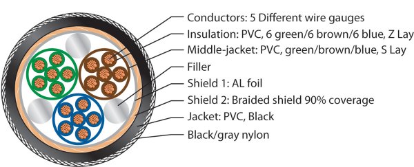
Guys-The only thing I did here was remove the existing power cord that Krell sent me and replace it with the Pangea power cord. Gary said something to the effect there was nothing out of the ordinary with regards to the construction of the Pangea, but if you compare the construction to a *normal* power cord, they are not in the same league. A regular power cord has three twisted conductors and may or may not have any shielding wrapped around the conductors. Pretty simple stuff. Here is what the Pangea looks like inside:

PGAC9_DIA-Large.jpg

I can always cut the power cord that Krell sent me open and take pictures of what it looks like inside if anyone is really interested. I think they (Krell) just sent me some cheesy power cord they had laying around and not a power cord that really should be used with the KSA-250.

With regards to my power, I have a separate 100A panel that feeds my addition where my listening room is located. The cable runs from my panel to my wall are pretty short. The 20A circuit that feeds my KSA-250 was installed fairly recently just for the KSA-250. The wiring job inside my panel is the neatest wiring job I have ever seen. I'm not making any claims that the new power cord has made my soundstage grow ten feet in each direction and the bass goes deeper, tighter and leaps over small buildings with a single bound. I'm just reporting that the power transformer on the KSA-250 is much more quiet now than with the regular power cord and for that I'm grateful.
 
Orb

There is NO relation between the mains (input) and the output of a double conversion system. A true Double Conversion UPS does not work on the main it simply uses it to charge the batteries. I suppose but don't know if the PS Audio regenerator works the same way, the mains current is rectified. This rectified signal is fed to an inverter. What you read is the inverter output. The main could 50% percent THD and that wouldn't change the output of the double conversion UPS... Main AC can be even absent!

Frantz,

A Double Conversion UPS works on the mains when there is mains one the input - it is permanently charging the batteries when there is mains, that is being rectified and simultaneously driving the inverter that creates the perfect mains. In this mode there is a relation between input and output. It is possible to run it on batteries for a limited time, but Mep KSA250 will discharge them very fast! Do you intend us to run our systems on battery mode exclusively?
 
I can always cut the power cord that Krell sent me open and take pictures of what it looks like inside if anyone is really interested.

You shouldn't need to cut your old IEC line cord to tell if it was shielded or not. If it was shielded, it should have the word "SHIELDED" indelibly printed or molded on it. If it doesn't say it is, it's probably not.
 
Frantz,

A Double Conversion UPS works on the mains when there is mains one the input - it is permanently charging the batteries when there is mains, that is being rectified and simultaneously driving the inverter that creates the perfect mains. In this mode there is a relation between input and output. It is possible to run it on batteries for a limited time, but Mep KSA250 will discharge them very fast! Do you intend us to run our systems on battery mode exclusively?

microstrip

Orb's first post wasn't too clear, I understand his points after clarification. Funny enough that is exactly how my former Telco grade worked.. Mpst of the time from the Batteries not because of any audible consequences but because of the price of Diesel. Running the generator all the time wasn't a good propostion and at the time we had less than 4 hours of electricity a day. In my case the UPS would send a signal to the generator to start it if the batteries level was getting too low. So the deal was to run the batteries when you really needed them and run the house for the most part on batteries ... more common that you would think in some countries. Things have changed substantially and people enjoy now between 8 and 12 hours of Grid power a day, in most places. At that rate people function even more on batteries.

I very well know how a double conversion works and I repeat for the most part there is no relation between the input and output Power quality. That is the main idea behind Double conversion.

Was there any audible difference on running the inverter on the batteries or on the rectified mains?
 

About us

  • What’s Best Forum is THE forum for high end audio, product reviews, advice and sharing experiences on the best of everything else. This is THE place where audiophiles and audio companies discuss vintage, contemporary and new audio products, music servers, music streamers, computer audio, digital-to-analog converters, turntables, phono stages, cartridges, reel-to-reel tape machines, speakers, headphones and tube and solid-state amplification. Founded in 2010 What’s Best Forum invites intelligent and courteous people of all interests and backgrounds to describe and discuss the best of everything. From beginners to life-long hobbyists to industry professionals, we enjoy learning about new things and meeting new people, and participating in spirited debates.

Quick Navigation

User Menu