My new project : phono preamp
- Thread starter Wardsweb
- Start date
You are using an out of date browser. It may not display this or other websites correctly.
You should upgrade or use an alternative browser.
You should upgrade or use an alternative browser.
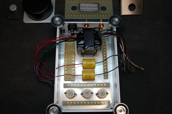
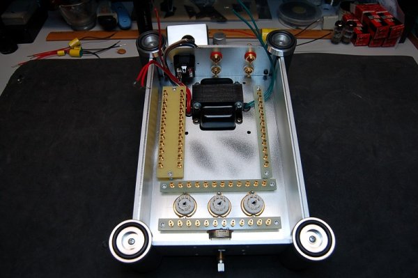
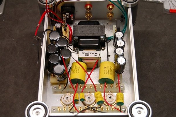
Any concern about the transformer (or is that another choke?) and choke in the chassis causing hum in the signal path?
Any concern about the transformer (or is that another choke?) and choke in the chassis causing hum in the signal path?
No, being this isn't my first rodeo. "Best practices" wiring and layout are time tested implementations that have given me great success in the past. Things like separating power and signal wires (both shielded), separate ground paths for power and signal, and plenty of filtering in the power circuit are just some of the techniques. I used a similar transformer and the same choke in my linestage.
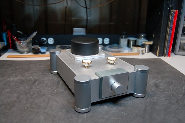
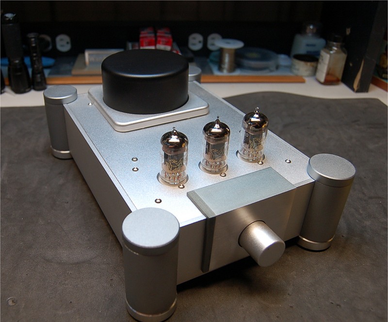
So what was that pretty case before you repurposed it?
And what is in the toroid enclosure on top if the transformer is inside?
And what is in the toroid enclosure on top if the transformer is inside?
No, being this isn't my first rodeo. "Best practices" wiring and layout are time tested implementations that have given me great success in the past. Things like separating power and signal wires (both shielded), separate ground paths for power and signal, and plenty of filtering in the power circuit are just some of the techniques. I used a similar transformer and the same choke in my linestage.
Sorry, did not mean to give offense. I couldn't tell what if any of the caps and wires were signal wires nor did I know your experience level (though obviously pretty high!)
My first rodeo was long ago but I've not ridden for years. Took fifth in bareback at KC finals, high as I ever got. One more reason to stay in engineering.
No offense taken. Just trying to give quick snap shot of design condensed from decades of experience.
By the way, I stopped riding bulls at Logan Huffman 30 years ago. My body thanks me now.
So what was that pretty case before you repurposed it?
And what is in the toroid enclosure on top if the transformer is inside?
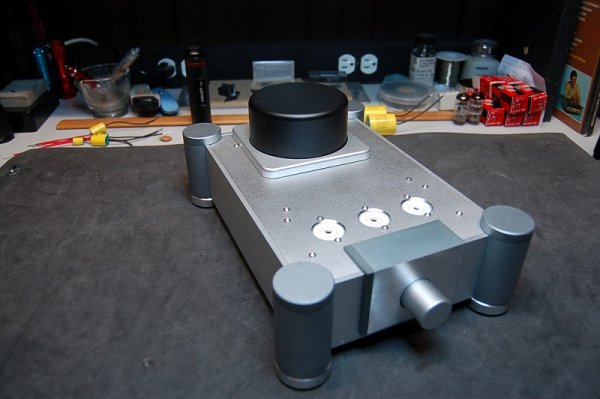
The enclosure is new and sourced out of China. It can be used for several designs depending on how the chassis is cut. I ordered it with blank panels, so I could do a custom layout. I've seen it used for preamps, headphone amps and DACs.
The original chassis design lends itself to the toroid enclosure. I took my transformer and mounted it upside down and recessed it into the space afforded me by the transformer cover.
Ah, somehow I thought it was a used unit when you said ebay. May bad  . Good to know nice looking enclosures like that are readily purchasable.
Hi
Do you have a schematic that you are following ? The rule of thumb for capacitance is 1000 uf for every amp of current, and its common for
inductance in the form of a choke to supply the valve anodes. the second transformer is I take for the 6.3v heaters.
All the best with your project.
Do you have a schematic that you are following ? The rule of thumb for capacitance is 1000 uf for every amp of current, and its common for
inductance in the form of a choke to supply the valve anodes. the second transformer is I take for the 6.3v heaters.
All the best with your project.
I have read that and other rules of thumb for capacitance but never quite understood them. If you have an ideal current source at twice the line frequency as might come from a typical rectifier then you get a large change in voltage if you assume only discharge during half the period. If you assume an ideal voltage source then the capacitance doesn't matter. In the real world in-between there are a myriad of variables that influence the choice in decoupling capacitance, including source and load impedance, charge and discharge rate, PSRR (DC and wideband) of the circuit, etc.
I have read that and other rules of thumb for capacitance but never quite understood them. If you have an ideal current source at twice the line frequency as might come from a typical rectifier then you get a large change in voltage if you assume only discharge during half the period. If you assume an ideal voltage source then the capacitance doesn't matter. In the real world in-between there are a myriad of variables that influence the choice in decoupling capacitance, including source and load impedance, charge and discharge rate, PSRR (DC and wideband) of the circuit, etc.
You have described it well, its a good rule of thumb as it defines the amperage required of the rectifier diodes.
when placed to charge and maintain capacitors whilst also switching AC.
Last edited:
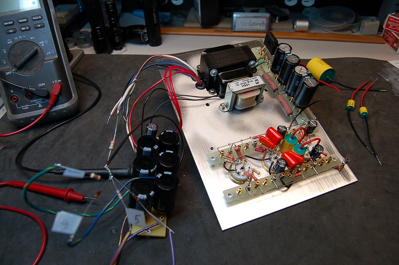
Life has a way of taking over. Well after months and a day of rain, I have made some progress on the phone stage. I need to determine some resistor values in the power supply and then I can install the board and clean up the wiring. The end draws near.

Similar threads
- Replies
- 2
- Views
- 410
- Replies
- 0
- Views
- 338
- Replies
- 3
- Views
- 1K
- Replies
- 18
- Views
- 724


