Five years ago on this very day, I quit my job as a software engineer.
As I reflect on that, I must mention that my wife is a living saint. I don't know how the spouses of creatives survive the insanity of journeys like the one I've been on, or the 23 years that we've been together for that matter. If ever so inclined, well... she'd have quite a story of her own to tell.
When we last left our hero, he'd demonstrated that he could make a driver that in fact played music, something nobody (not even himself) actually believed was going to happen.
Here's how it measured:
SPL: 95.57 1W/1m
Re: 7.67 Ohms
Fs: 19.51Hz
Qts: .1817
Qes: .1902
Qms: 4.071
Le: .3429mH (10k)
Mmd: 18.5g
Mms: 23.51g
Vas: 19.2 cu ft
I didn't know what to do with most of the Thiele Small parameters at the time, but was assured that I should be very pleased with these values.
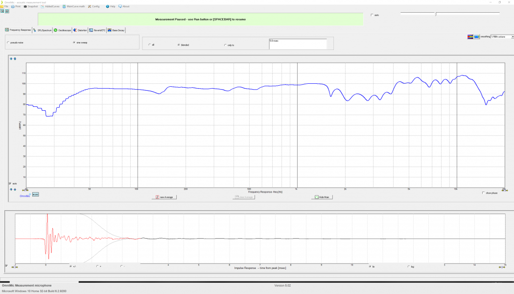
This is a tone sweep (measured just as seen in the prior video, drivers on the floor, with a separate sub filling in below 100Hz) at a 6-7ft listening position, using OmniMic software:
Everyone hoped at this point that I'd construct the cabinet and a finished loudspeaker, but to great disappointment, I didn't. I doubled down on the driver, instead. What I'd somehow made was much more than a curiosity, to play occasionally for friends. I felt that if I just pushed the development of it another cycle further, something of actual critical merit was within my reach. I simply couldn't pass that possibility up. I had my annual bonus to draw upon for the development. My decision renewed all of the old doubts of friends and loved ones, but the cabinetry would have to wait a while longer.
Regarding the field coil, it wasn't all good news. The prototype didn't include a phase plug to mitigate wave cancellations, the addition of which would surely improve performance. The motor became very hot after 4 hours on a bench supply at 12VDC. It wouldn't melt the carpet it was on, but if I let them run for a full day it was not uncommon for the voice coil to begin to rub slightly against the gap, and the steel became very uncomfortable to the touch. Sealing up that kind of heat in a thick wooden box seemed most unwise.
The brass and hardwood basket was long on fun and interest, but short on stiffness and strength. Wood breathes and flexes with changes in temperature and humidity, and those small changes correlate with shifts in alignment of the moving assembly. The basket instead needed to be metal, or carbon fiber, or stone. All were considered, and carbon fiber composite and metal versions were designed and made. Carbon fiber was eventually dismissed, in favor of aluminum.
After months of use, the silk thread spider began to sag and eventually, it no longer held the moving mass centered in the gap. That misfortune marked the end of the prototype driver and countless wonderful hours of listening to them play.
Lastly, the driver Qts was too low - but more on that topic, in a future post.
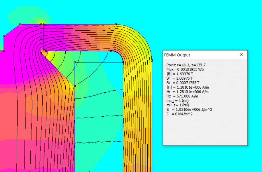
It was time to redesign the motor steel and solenoid. Considerations in that redesign were as follows:
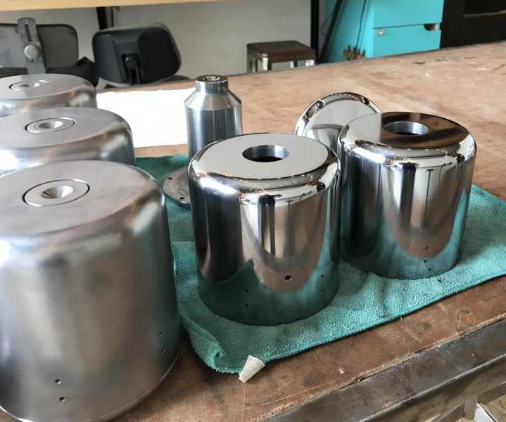
The fires of industry were stoked, and a month later four full sets of new steel arrived at my doorstep, in a heavy crate. Knowing that I may opt for open baffle, or perhaps a partially glass cabinet, I spent long exhausting days sanding away all of the tool marks and polishing the raw steel housings:
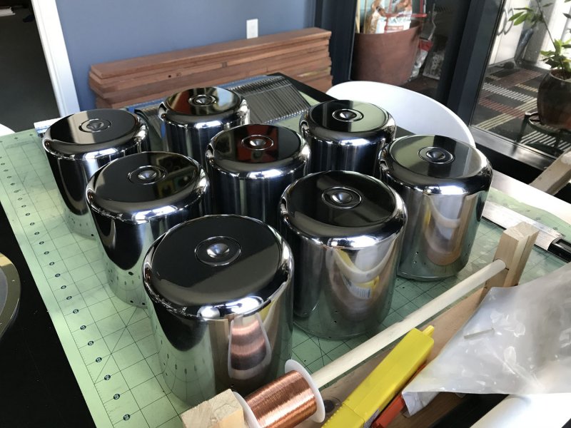
Pro tip: it doesn't matter how much mild steel is polished, or microcrystalline wax is applied to it. As dependable as are death and taxes, it will eventually rust.
The entire driver was to be reconsidered, if this was going to rise to the level of a serious production driver. I spent months working and reworking in the digital space, often with the steady counsel of my spiritual guide, Leonard the Cat.
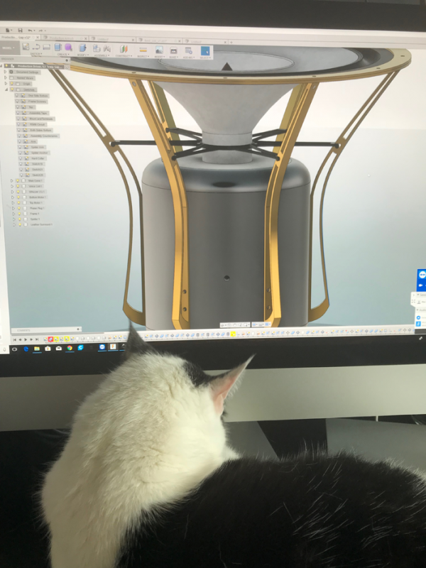
Work performance began to suffer, as I'd steal away to conference rooms when I had the chance, mostly to read... endlessly reading to internalize and understand what really mattered in the design of a loudspeaker, and further CAD/CAM models of the driver instead of writing code. The basket became more of a frame, evolved into a sink designed to pull as much heat away from the motor as possible. Along with many other areas of fabrication at the time, waterjet cutting had become a relatively affordable process for small manufacturers, which was how all of the frame and flange pieces were, and still are, made.
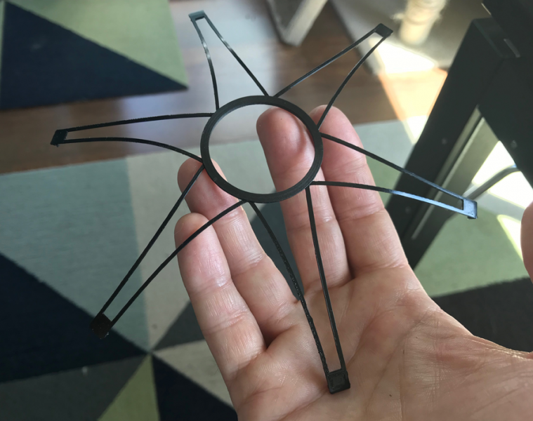
Thankfully, 3D printing had followed suit, and the spider was in principle kept as it was. I bought a large format FDM printer, and experimented with many different materials before settling on a thermal polyurethane developed with the high demands of the healthcare and auto industries in mind. It was flexible, heat tolerant, easy to work with, and would effectively never degrade in this application. Other advantages of TPU over silk thread were its linear compliance and elasticity. That elasticity helped address what I've always felt is a disadvantage of common, concentric roll cloth spiders. Typically, spiders just hang as dead weight on the voice coil. A flexible lattice could overcome some measure of that, holding the entire moving mass in very light tension for a more lively and sensitive presentation. Fractions of a millimeter in its diameter made audible and measurable differences, affecting the free air resonance, distortion, linearity, impulse response, and so on. Several designs were tried, and dozens of varying diameters to arrive at the lattice I use today. This was the first design that I made, with a feather-light carbon fiber composite collar at its center:
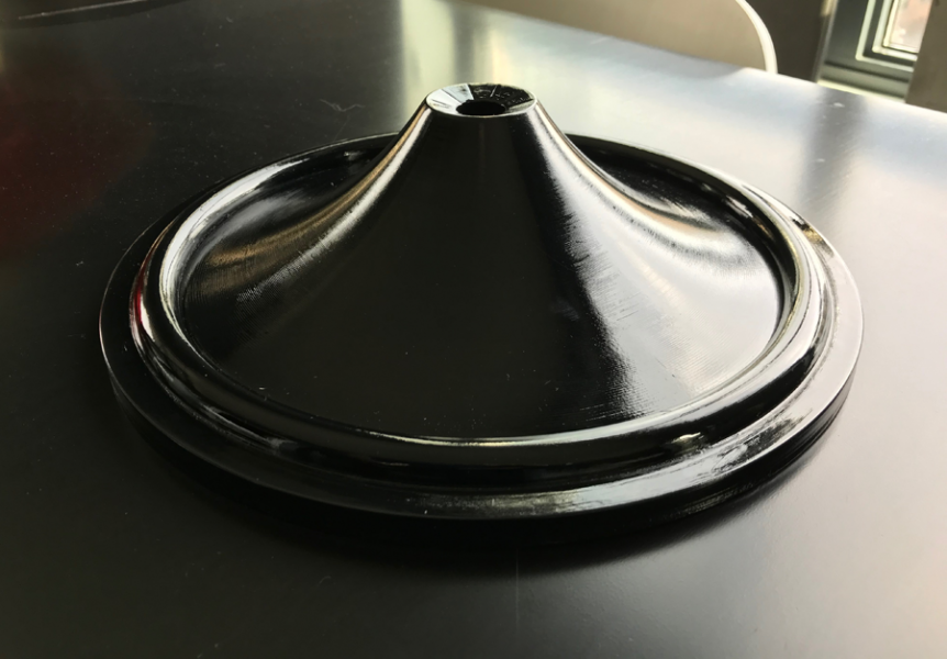
With the addition of large format 3D printing, molds were much improved. Kinwashi paper became Hosho washi, throughout. This is a two part mold that slip-fits the cone section at the surround half-roll, similar to the design that is still used today:
While it doesn't show in that picture, I had by now utterly destroyed our dining room table. It was a maze of deep scratches and dents, the worst of them inked in with a black sharpie pen. An SLA resin printer was added to the shop soon after, for terminal post mountings, the phase plug and other cosmetically visible parts.
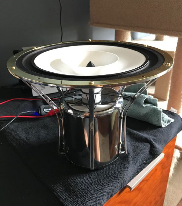
I'd now invested years and literally thousands of hours of time and effort toward this goal. The amalgam of it all came together one day to produce this, here seen being measured for the first time in DATS:
This is the measurement that was pulled a few minutes after that picture was taken:
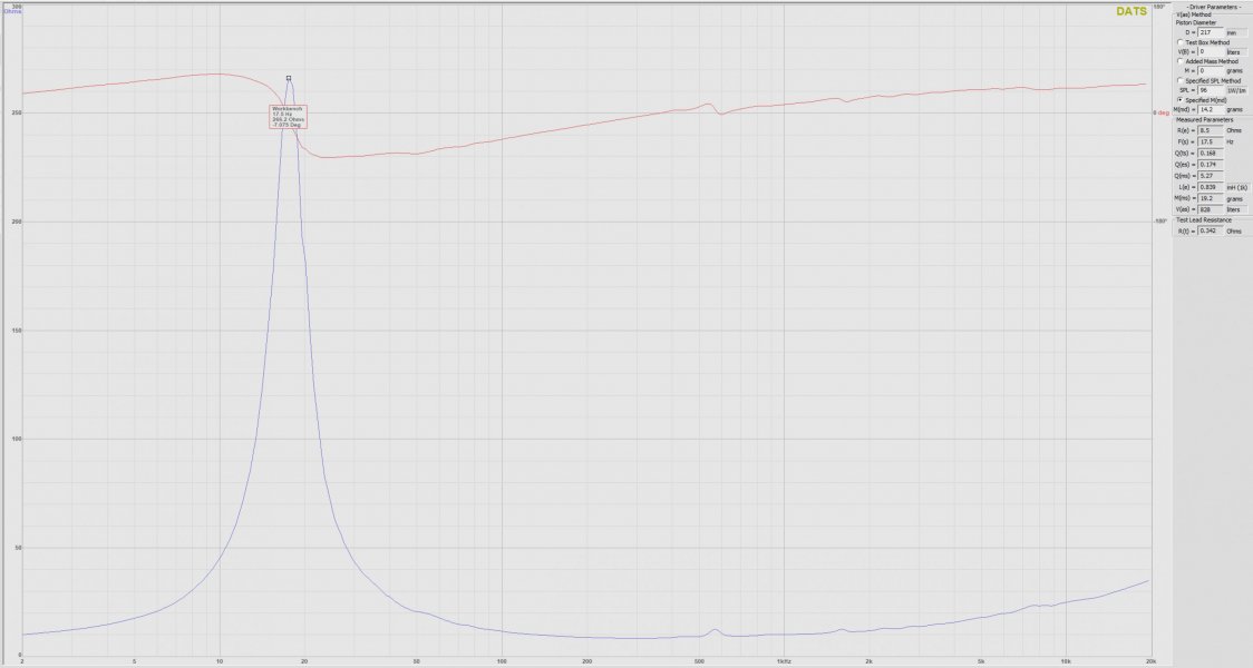
SPL: 96 1W/1m
Re: 8.5 Ohms
Fs: 17.5Hz
Qts: .168
Qes: .174
Qms: 5.27
Le: .839mH (1k)
Mmd: 14.2g
Mms: 19.2g
Vas: 29.2 cu ft (828 liters)
It was now time to design and build a cabinet, and at long last, see what this driver could do.
As I reflect on that, I must mention that my wife is a living saint. I don't know how the spouses of creatives survive the insanity of journeys like the one I've been on, or the 23 years that we've been together for that matter. If ever so inclined, well... she'd have quite a story of her own to tell.
When we last left our hero, he'd demonstrated that he could make a driver that in fact played music, something nobody (not even himself) actually believed was going to happen.
Here's how it measured:
SPL: 95.57 1W/1m
Re: 7.67 Ohms
Fs: 19.51Hz
Qts: .1817
Qes: .1902
Qms: 4.071
Le: .3429mH (10k)
Mmd: 18.5g
Mms: 23.51g
Vas: 19.2 cu ft
I didn't know what to do with most of the Thiele Small parameters at the time, but was assured that I should be very pleased with these values.
This is a tone sweep (measured just as seen in the prior video, drivers on the floor, with a separate sub filling in below 100Hz) at a 6-7ft listening position, using OmniMic software:

Everyone hoped at this point that I'd construct the cabinet and a finished loudspeaker, but to great disappointment, I didn't. I doubled down on the driver, instead. What I'd somehow made was much more than a curiosity, to play occasionally for friends. I felt that if I just pushed the development of it another cycle further, something of actual critical merit was within my reach. I simply couldn't pass that possibility up. I had my annual bonus to draw upon for the development. My decision renewed all of the old doubts of friends and loved ones, but the cabinetry would have to wait a while longer.
Regarding the field coil, it wasn't all good news. The prototype didn't include a phase plug to mitigate wave cancellations, the addition of which would surely improve performance. The motor became very hot after 4 hours on a bench supply at 12VDC. It wouldn't melt the carpet it was on, but if I let them run for a full day it was not uncommon for the voice coil to begin to rub slightly against the gap, and the steel became very uncomfortable to the touch. Sealing up that kind of heat in a thick wooden box seemed most unwise.
The brass and hardwood basket was long on fun and interest, but short on stiffness and strength. Wood breathes and flexes with changes in temperature and humidity, and those small changes correlate with shifts in alignment of the moving assembly. The basket instead needed to be metal, or carbon fiber, or stone. All were considered, and carbon fiber composite and metal versions were designed and made. Carbon fiber was eventually dismissed, in favor of aluminum.
After months of use, the silk thread spider began to sag and eventually, it no longer held the moving mass centered in the gap. That misfortune marked the end of the prototype driver and countless wonderful hours of listening to them play.
Lastly, the driver Qts was too low - but more on that topic, in a future post.
It was time to redesign the motor steel and solenoid. Considerations in that redesign were as follows:
- Magnetic flow doesn't like to negotiate sharp corners, as with the prototype geometry.
- Develop a two piece assembly to improve the physical uniformity of the gap
- Refine the steel geometry to achieve a 1.6T flux density or better in the gap
- Use a higher gauge wire, in the hope that it may offer a cooler running motor

The fires of industry were stoked, and a month later four full sets of new steel arrived at my doorstep, in a heavy crate. Knowing that I may opt for open baffle, or perhaps a partially glass cabinet, I spent long exhausting days sanding away all of the tool marks and polishing the raw steel housings:


Pro tip: it doesn't matter how much mild steel is polished, or microcrystalline wax is applied to it. As dependable as are death and taxes, it will eventually rust.
The entire driver was to be reconsidered, if this was going to rise to the level of a serious production driver. I spent months working and reworking in the digital space, often with the steady counsel of my spiritual guide, Leonard the Cat.

Work performance began to suffer, as I'd steal away to conference rooms when I had the chance, mostly to read... endlessly reading to internalize and understand what really mattered in the design of a loudspeaker, and further CAD/CAM models of the driver instead of writing code. The basket became more of a frame, evolved into a sink designed to pull as much heat away from the motor as possible. Along with many other areas of fabrication at the time, waterjet cutting had become a relatively affordable process for small manufacturers, which was how all of the frame and flange pieces were, and still are, made.
Thankfully, 3D printing had followed suit, and the spider was in principle kept as it was. I bought a large format FDM printer, and experimented with many different materials before settling on a thermal polyurethane developed with the high demands of the healthcare and auto industries in mind. It was flexible, heat tolerant, easy to work with, and would effectively never degrade in this application. Other advantages of TPU over silk thread were its linear compliance and elasticity. That elasticity helped address what I've always felt is a disadvantage of common, concentric roll cloth spiders. Typically, spiders just hang as dead weight on the voice coil. A flexible lattice could overcome some measure of that, holding the entire moving mass in very light tension for a more lively and sensitive presentation. Fractions of a millimeter in its diameter made audible and measurable differences, affecting the free air resonance, distortion, linearity, impulse response, and so on. Several designs were tried, and dozens of varying diameters to arrive at the lattice I use today. This was the first design that I made, with a feather-light carbon fiber composite collar at its center:

With the addition of large format 3D printing, molds were much improved. Kinwashi paper became Hosho washi, throughout. This is a two part mold that slip-fits the cone section at the surround half-roll, similar to the design that is still used today:

While it doesn't show in that picture, I had by now utterly destroyed our dining room table. It was a maze of deep scratches and dents, the worst of them inked in with a black sharpie pen. An SLA resin printer was added to the shop soon after, for terminal post mountings, the phase plug and other cosmetically visible parts.
I'd now invested years and literally thousands of hours of time and effort toward this goal. The amalgam of it all came together one day to produce this, here seen being measured for the first time in DATS:

This is the measurement that was pulled a few minutes after that picture was taken:

SPL: 96 1W/1m
Re: 8.5 Ohms
Fs: 17.5Hz
Qts: .168
Qes: .174
Qms: 5.27
Le: .839mH (1k)
Mmd: 14.2g
Mms: 19.2g
Vas: 29.2 cu ft (828 liters)
It was now time to design and build a cabinet, and at long last, see what this driver could do.
Last edited:


