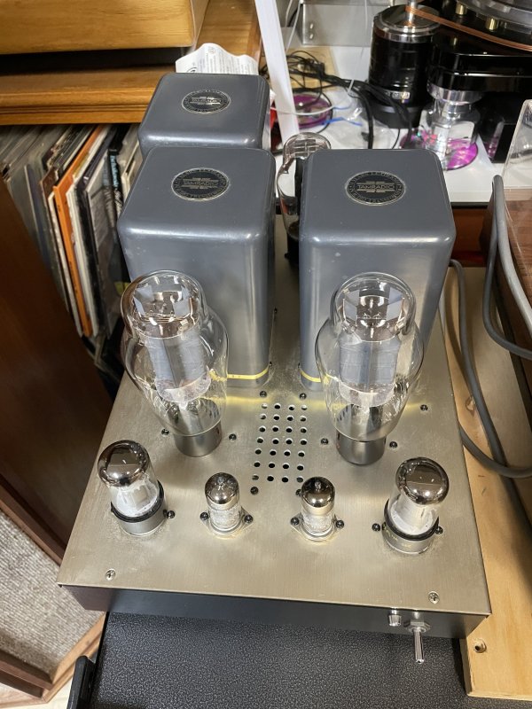
SET amp owners thread

Thanks for idea Ralph. Are they position constrained (power supply, interstage, output), or can they go wherever there's value overlap?
They can go anywhere the ratings allow. They don't need a warmup since they have zero temperature coefficient, and their dissipation factor is similar to Teflon with a ruler flat curve when that is charted with respect to temperature.
I don’t know about how much you “need”. I have 18 SET watts into a 16 ohm load speaker that is 105 dB. I might use 10% of the power when I have it cranking, but the beauty of that is that the distortion is super low. it’s nice to be able to use a mere fraction of an amplifier’s power rating knowing you have the headroom but not needing it to keep distortion low.
When the amplifier power is at 10%, its incorrect to say the distortion is 'super low'... Its more accurate to simply say there is 'distortion that isn't too high'. As you know, its all about that first Watt, but even with 18 Watt at clipping, the 1 Watt distortion will be quite measurable and audible.
The other tweak to try is to replace the polypropylene capacitors that bypass the electrolytic capacitors with a Jensen copper foil in oil of the same value. I did that in my Cary amps and liked it a lot. Use the same value and connections as the polypropylene capacitor being replaced.
Bypassing coupling caps is always tricky! The reason is the caps can have different speeds so this can contribute to smearing at high frequencies. The more transparent the system the easier this is to hear (its also measurable, not that that matters on this thread...). For this reason, to get the best out of a coupling cap you just have to give it your best shot and no bypassing. Generally this means a Teflon cap because:

Oil fill caps that we have tested have often displayed electrical leakage, although all the examples we've tested with this problem have been paper and oil. We've not encountered this problem with the ODAM caps from VH Audio. If the cap has leakage (which is not physical leaking) it will be a small DC Voltage at the output of the part where there should be none at all. This can throw off the operating point of the tube receiving the signal (such as the bias of a power tube). In the case of a power tube this can result in shorter tube life, distortion (because if the tube is over-biased distortion will rise) and possibly damage to an output transformer and/or power transformer. You don't run into this problem with Teflon parts.

Coupling caps are a good reason to consider direct-coupling between the driver and power tube. If the driver is a cathode-follower, the power tube can obtain its bias from the driver tube and a much smaller coupling cap can be employed at the input to the driver tube. The smaller the coupling cap you can use without running into a LF cutoff problem, the more transparent the capacitor can be.
 
Bypassing coupling caps is always tricky! The reason is the caps can have different speeds so this can contribute to smearing at high frequencies. The more transparent the system the easier this is to hear (its also measurable, not that that matters on this thread...). For this reason, to get the best out of a coupling cap you just have to give it your best shot and no bypassing. Generally this means a Teflon cap because:

Oil fill caps that we have tested have often displayed electrical leakage, although all the examples we've tested with this problem have been paper and oil. We've not encountered this problem with the ODAM caps from VH Audio. If the cap has leakage (which is not physical leaking) it will be a small DC Voltage at the output of the part where there should be none at all. This can throw off the operating point of the tube receiving the signal (such as the bias of a power tube). In the case of a power tube this can result in shorter tube life, distortion (because if the tube is over-biased distortion will rise) and possibly damage to an output transformer and/or power transformer. You don't run into this problem with Teflon parts.
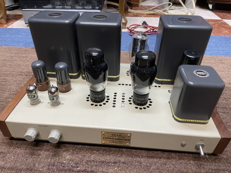
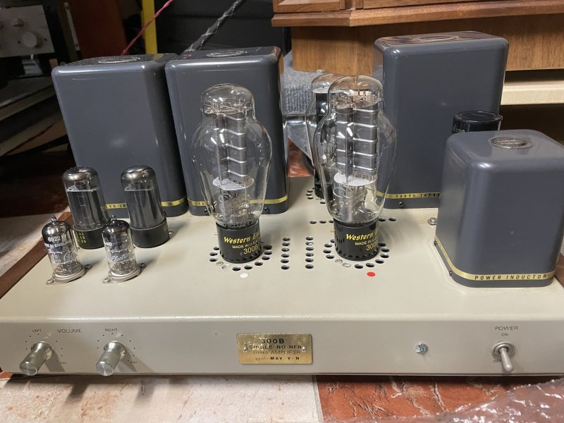
Please refer to photo in post #3530. Perhaps there is a misunderstanding.

The polypro caps I was referring to are on the electrolytic filter caps for the power supply. This can be confirmed by noting the bleed resistor across the same terminals as the polypro bypass caps. So, it is an electrolytic cap for power supply filter and holdup with a small bypass for higher frequency noise on the supply output.

My suggestion is to try other types of bypass capacitors - in that application. I found that the Jensen copper foil in oil worked quite well and actually "improved" the sound of the amp (to my ears, YMMV).

Bypassing a coupling cap would be problematic since it is essentially two different caps in parallel in the direct signal path. Not sure what that would sound like. I was not suggesting a bypass on a coupling cap nor a paper and oil type capacitor.
Bypassing filter caps good.
Bypassing coupling caps bad.

Bypassing power supply caps can have very measurable as well as audible effects. Its not trivial.
 
  • Like
Reactions: DasguteOhr
Please refer to photo in post #3530. Perhaps there is a misunderstanding.

The polypro caps I was referring to are on the electrolytic filter caps for the power supply. This can be confirmed by noting the bleed resistor across the same terminals as the polypro bypass caps. So, it is an electrolytic cap for power supply filter and holdup with a small bypass for higher frequency noise on the supply output.

My suggestion is to try other types of bypass capacitors - in that application. I found that the Jensen copper foil in oil worked quite well and actually "improved" the sound of the amp (to my ears, YMMV).

Bypassing a coupling cap would be problematic since it is essentially two different caps in parallel in the direct signal path. Not sure what that would sound like. I was not suggesting a bypass on a coupling cap nor a paper and oil type capacitor.
Increasing the size of a coupling capacitor is not a good idea. Because the coupling capacitor and grid leak resistor represent a filter for the next tube amplifier stage. If you increase it, you change the lower limit frequency and the charging and discharging times. This results in poorer pulse reproduction (square wave). You load the amplifier with frequencies that you probably cannot hear. It can make sense to remove the coupling capacitor before the input stage, assuming your preamplifier is not DC coupled (without a capacitor).no capacitor is the best capacitor;)
P.S
 
Last edited:
  • Like
Reactions: Atmasphere
It can make sense to remove the coupling capacitor before the input stage, assuming your preamplifier is not DC coupled (without a capacitor).no capacitor is the best capacitor;)
P.S
We are on the same page with this which is why our designs are specifically designed to minimize the number of capacitors in the signal path, and where they appear, to minimize their values as smaller caps have lower inductance so can be more transparent. Our preamps have a direct-coupled vacuum tube output to this end and our amps a direct-coupled input. Our amps have only one matched pair of coupling caps in the entire circuit.

A lot of this is easy to implement in an SET and there are already SETs that might have only one coupling cap in the design. But if that's the case, that coupling cap is the one between the driver and output tube so its usually a fairly large value which will be less transparent. Since cost really isn't the object here while the sound quality is, the thing to do is have a bipolar power supply for the Voltage amplifier and driver circuit. This will allow for a relatively small (by an order of magnitude) coupling cap between the Voltage amplifier and the driver, while the drive is direct-coupled to the power tube. The power tube would then be obtaining its bias from the driver tube (cathode follower) which because it is a cathode follower, will have no problems with and of the difficulties associated with driving a low mu triode power tube with possibly a high grid capacitance. You would then set the bias parameter on the grid of the driver tube.

The advantage of this approach (and using a B- supply) is that it is fail safe. A failure of the driver tube would result in cutoff of the power tube, preventing damage to an expensive part. Its also quite low distortion since a regular driver will have distortion associated with driving the power tube. An additional plus is that if A2 operation is desired the driver has the robust linearity to handle grid current. This means you can get more power with no downside to linearity. So you could get 10-12 Watts from a single 300b without shortening the life of the power tube.

This means that all the gain has to come from the Voltage amplifier, but SETs usually don't need that much gain to start with unless its a higher power design. The gain could come from a single 6SL7 section, or a cascode circuit using a 6SN7.

The advantage of this approach is you can get lower distortion and wider bandwidth than you can with a conventional RC coupled approach or by using interstage transformers. IME since you really don't want to saturate the OPT with low frequencies it can't pass, the coupling cap value used could be less than 0.022uf and the circuit would still have bandwidth lower than any OPT could pass.
 
  • Like
Reactions: RCanelas and we421a
Increasing the size of a coupling capacitor is not a good idea. Because the coupling capacitor and grid leak resistor represent a filter for the next tube amplifier stage. If you increase it, you change the lower limit frequency and the charging and discharging times. This results in poorer pulse reproduction (square wave). You load the amplifier with frequencies that you probably cannot hear. It can make sense to remove the coupling capacitor before the input stage, assuming your preamplifier is not DC coupled (without a capacitor).no capacitor is the best capacitor;)
P.S
I am all cornfused. Not sure how discussion of coupling capacitors is related to a reply and discussion of bypass capacitors used solely on the electrolytic capacitors in a power supply.

Coupling caps are in the signal path.

I am not saying anything about coupling capacitors.

I do agree that coupling capacitors should be correctly sized and the type should be chosen according to many factors (cost goals, reliability, leakage, sound characteristics, etc).
I think the comments are meant to clarify only and are not reactive.
 
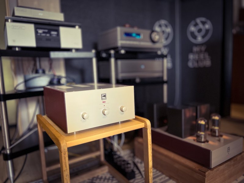
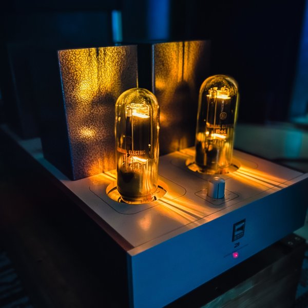
IMG_2603.jpegIMG_2634.jpegWent over to Leifs today to pick up a pair of WE 300b and Takatsuki 300b to be tested in my 300b amps. The wife and kids are staying in the cabin up north in the Lofoten islands a couple of weeks and I have time for some serious testing. The shoot out will be between Full Music 300b (came with the amps),WE and Takatsuki.

View attachment 133007View attachment 133008

One of the Takatsuki tubes is faulty so can’t test those, however the WE are singing flawlessly. As the rest of the family is away, I have full freedom of speaker placement.
 
One of the Takatsuki tubes is faulty so can’t test those, however the WE are singing flawlessly. As the rest of the family is away, I have full freedom of speaker placement.
Lovely Room!!
 
  • Like
Reactions: crosswind
Yes lovely. Is it the firewood diffuser that caught your eye John?
You have me pegged Greg! All my intricate little secrets/idiosyncrasies...
 
Yes lovely. Is it the firewood diffuser that caught your eye John?
What about steam powered amps? Hooked up to my boiler? Have to be a few relays along the way...LOL!!
 
What about steam powered amps? Hooked up to my boiler? Have to be a few relays along the way...LOL!!
Erecting your own power station is a novel solution to the contaminated/inadequate power issue. Can you get your wood boiler up to 5000psi? A steam powered Rankine Cycle plant with first and second reheat should provide adequate power for your Gryphon amplification. Cooling water from the creek in the backyard will help with system efficiency.

Why are you lurking on the SET thread? Are you SET curious? I know where to get a nice pair of 46 monos. Maybe you could run on a battery if you take this route.;)
 
  • Love
Reactions: John T

About us

  • What’s Best Forum is THE forum for high end audio, product reviews, advice and sharing experiences on the best of everything else. This is THE place where audiophiles and audio companies discuss vintage, contemporary and new audio products, music servers, music streamers, computer audio, digital-to-analog converters, turntables, phono stages, cartridges, reel-to-reel tape machines, speakers, headphones and tube and solid-state amplification. Founded in 2010 What’s Best Forum invites intelligent and courteous people of all interests and backgrounds to describe and discuss the best of everything. From beginners to life-long hobbyists to industry professionals, we enjoy learning about new things and meeting new people, and participating in spirited debates.

Quick Navigation

User Menu

Steve Williams
Site Founder | Site Owner | Administrator
Ron Resnick
Site Co-Owner | Administrator
Julian (The Fixer)
Website Build | Marketing Managersing