Spectral DMA 150 Upgrade

Jon Q

VIP/Donor
Jun 16, 2019
90
43
150
Lisbon
Hi

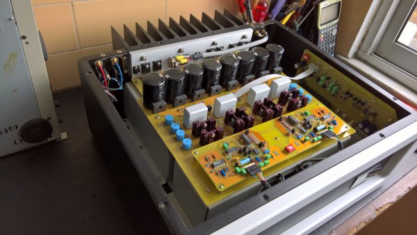
I recently bought, Spectral DMA 150 series I, in excellent condition. I like your signature, but without focus and sound closed. Curiously one channel is better than the other.

The doubt is .... if it is possible to upgrade to series II or it is preferable to upgrade (capacitors, resistors, internal wire .....).

jon
 

Attachments

  • DMA150_1.jpg
    DMA150_1.jpg
    2 MB · Views: 186
  • Like
Reactions: Rocoa and alecm

TooCool4

Well-Known Member
Feb 7, 2013
960
939
925
England
You can always check with your local dealer if it's possible to upgrade to series II. You can send it back to Spectral for a service if you think one channel sounds better than the other, with the help of your local dealer as Spectral will not deal with you directly.
 

Jon Q

VIP/Donor
Jun 16, 2019
90
43
150
Lisbon
You can always check with your local dealer if it's possible to upgrade to series II. You can send it back to Spectral for a service if you think one channel sounds better than the other, with the help of your local dealer as Spectral will not deal with you directly.

Hi

There is a small problem, so far there are no dealer in Portugal.
In the last analysis, is to make an upgrade replacement of components, "capacitors... end of life".

jon
 

TooCool4

Well-Known Member
Feb 7, 2013
960
939
925
England
Cannot advise you on what to do next, but if you want Spectral to service it for you? You will have to find the nearest dealer to you.
 

Jon Q

VIP/Donor
Jun 16, 2019
90
43
150
Lisbon
I will check here in Europe if there is a possibility to upgrade to the series II

Thank you for your attention.
jon
 

TooCool4

Well-Known Member
Feb 7, 2013
960
939
925
England
Your nearest dealer is in Germany i think.

Good luck.
 

Jon Q

VIP/Donor
Jun 16, 2019
90
43
150
Lisbon
After unsuccessful attempt to contact the representative in Germany about upgrading to series II. I decided to upgrade this recent purchase, for my system.

Replacement of electrolytic capacitors. From several models that were tested including the original reference (10000uF / 80V from nippon chemicon, SMH series), I opted for the nichicon KS (M) for its sound performance. From KME 1000uF / 63V and 470uF / 100V series has been replaced by the nichicon (KW) series. These capacitors are from the power supply of the voltage amplifier and power supply to the AD842. Also on the protection circuit board the electrolytic capacitors were replaced.

The Spectral DMA 150, uses Vishay RN55D resistors (1% - 100ppm). I like this series but prefer the RN55E version (0.1% - 25ppm). These resistors (RN55D) were replaced by the RN55E version, those that work in current mode, and those that work in voltage mode, were replaced by RC55Y series of welwyn (0.1% - 15ppm), signal and feedback path.

The resistances of the main board, (circuit protection) and protection board kept everything the same.

Other resistors have been replaced from power supply for output mosfet in this case I chose the Vishay serie RS 5W 1%.
("... Interestingly, the sense of orientation of the resistances has an influence on the sound result. In this case I chose the opposite direction of the screen printing, the current through which it circulates ...")!!!

The rectifying bridges for output mosfet, I opted for another ref. (GBU806 from DIODES INC.) For the voltage amplifier, I prefer ultra fast diodes but not schottky diodes. It was designed four pcb to place four diodes (RHRP860) and adapt to the motherboard. This is because there are no ultra-fast bridges on the market with the same original box type.

The suspension of the transformers has been updated, the original was very hard.

As soon as possible, I put photos...

cheers
 
Last edited:

TooCool4

Well-Known Member
Feb 7, 2013
960
939
925
England
Nice one Jon Q, how are they sounding?
 

Jon Q

VIP/Donor
Jun 16, 2019
90
43
150
Lisbon
pictures

replacement, suspension/absorber of transformer, passive components (capacitors, and carbon resistors, these have been replaced by the CPF 2 series). The rectifier diode bridges were also removed. The output mosfets were removed... later I explain the reason.


to be continued....
 

Attachments

  • 1 - Copy.jpg
    1 - Copy.jpg
    2.8 MB · Views: 191
  • 2 - Copy.jpg
    2 - Copy.jpg
    2.3 MB · Views: 183
  • 4 - Copy.jpg
    4 - Copy.jpg
    2.1 MB · Views: 174
  • 5 - Copy.jpg
    5 - Copy.jpg
    2.9 MB · Views: 163
  • 5.1 - Copy.jpg
    5.1 - Copy.jpg
    2.8 MB · Views: 147
  • 6.1 - Copy.jpg
    6.1 - Copy.jpg
    2.8 MB · Views: 139
  • 6.2 - Copy.jpg
    6.2 - Copy.jpg
    2.8 MB · Views: 130
  • 6.3 - Copy.jpg
    6.3 - Copy.jpg
    2.4 MB · Views: 124
  • 6.4 - Copy.jpg
    6.4 - Copy.jpg
    2.9 MB · Views: 144

Jon Q

VIP/Donor
Jun 16, 2019
90
43
150
Lisbon
protection board...
replacement of electrolytic capacitors and cleaning of power relay contacts
 

Attachments

  • 17.jpg
    17.jpg
    2.7 MB · Views: 90
  • 18.jpg
    18.jpg
    1.4 MB · Views: 90
  • 19.jpg
    19.jpg
    1.8 MB · Views: 87

Jon Q

VIP/Donor
Jun 16, 2019
90
43
150
Lisbon
With the help of an oscilloscope, here it was checked individually if there was any winding out of phase, being from one of the transformers, had even an inverted winding for one of the output mosfet.
Nothing serious, with the help of a small custom-made tool, was just reversing this winding. Curiously it was the channel that had the "closed sound". After this operation, the difference between the two channels was resolved.
 

Attachments

  • 30.jpg
    30.jpg
    2.7 MB · Views: 67
  • 31.jpg
    31.jpg
    2 MB · Views: 63
  • 32.jpg
    32.jpg
    1.8 MB · Views: 60

Jon Q

VIP/Donor
Jun 16, 2019
90
43
150
Lisbon
In the aluminum fixing panel (where the output mosfets are located) a ["chanfro" in Portuguese] was made, because the motherboard had one / two conductive lines, which had physical contact with the aluminum panel. its isolation was only by the varnish on the copper of the pcb. See picture 15.3.

Another feature also, annulled the original insulators, replacedin aluminum oxide (ceramic) from the manufacturer fischer elektronik.
 

Attachments

  • 11.jpg
    11.jpg
    2.4 MB · Views: 92
  • 15.0.jpg
    15.0.jpg
    2.2 MB · Views: 100
  • 15.1.jpg
    15.1.jpg
    1.1 MB · Views: 106
  • 15.2.jpg
    15.2.jpg
    2.6 MB · Views: 108
  • 15.3.jpg
    15.3.jpg
    430.2 KB · Views: 104

Jon Q

VIP/Donor
Jun 16, 2019
90
43
150
Lisbon
The pcb for the ultra fast diode rectifier bridges were designed exclusively for this amplifier.
I always gave preference to this type of diodes for this situation, its result is very neutral and very fast response the sound, here in Spectral the combination is really very very good.
In figure 16.3 it is possible to see the assembly of the 4 units, including the 8 new rectifying bridges of the power output transistors. (mosfets)

to be continued.....


cheers
 

Attachments

  • 16.1.jpg
    16.1.jpg
    1.5 MB · Views: 86
  • 16.2.jpg
    16.2.jpg
    2.7 MB · Views: 89
  • 16.3.jpg
    16.3.jpg
    2.7 MB · Views: 96
Last edited:

ack

VIP/Donor & WBF Founding Member
May 6, 2010
6,774
1,198
580
Boston, MA
Fascinating work! Congratulations! Envious. Love the tool that pushes the pin out. Just imagine, all these parts, beautiful execution and design cost some $5000 in the US when it came out
 

Jon Q

VIP/Donor
Jun 16, 2019
90
43
150
Lisbon
Fascinating work! Congratulations! Envious. Love the tool that pushes the pin out. Just imagine, all these parts, beautiful execution and design cost some $5000 in the US when it came out

Hi ack
Thank you.

Dear ack
One question, this model is the XLR input, pin 3 is +, and pin 2 is -.
The recent models of Spectral is same a conection? By rule, pin 2 is the positive and the negative pin 3, pin 1 is always the ground.
 

Jon Q

VIP/Donor
Jun 16, 2019
90
43
150
Lisbon
The cleaning the chassis and recovering the fuse holders. The wiring has also been replaced (mains 230V) with copper Wire Teflon Insulated ... the heatsink is also entitled to a shower

The wire, motherboard to chassi kept the same original wire (silver / teflon)

....
 

Attachments

  • 20.jpg
    20.jpg
    2.2 MB · Views: 88
  • 21.jpg
    21.jpg
    1.8 MB · Views: 82
  • 22.3.jpg
    22.3.jpg
    2 MB · Views: 86
  • 23.jpg
    23.jpg
    2.8 MB · Views: 80
  • 24.jpg
    24.jpg
    2.8 MB · Views: 85
  • 26.1.jpg
    26.1.jpg
    2.6 MB · Views: 85
  • 26.2.jpg
    26.2.jpg
    2.3 MB · Views: 97
  • 26.3.jpg
    26.3.jpg
    2.1 MB · Views: 100
  • 27.jpg
    27.jpg
    2.6 MB · Views: 97

TooCool4

Well-Known Member
Feb 7, 2013
960
939
925
England
Wow this all looks amazing Jon Q
 
  • Like
Reactions: jonstanza

About us

  • What’s Best Forum is THE forum for high end audio, product reviews, advice and sharing experiences on the best of everything else. This is THE place where audiophiles and audio companies discuss vintage, contemporary and new audio products, music servers, music streamers, computer audio, digital-to-analog converters, turntables, phono stages, cartridges, reel-to-reel tape machines, speakers, headphones and tube and solid-state amplification. Founded in 2010 What’s Best Forum invites intelligent and courteous people of all interests and backgrounds to describe and discuss the best of everything. From beginners to life-long hobbyists to industry professionals, we enjoy learning about new things and meeting new people, and participating in spirited debates.

Quick Navigation

User Menu

Steve Williams
Site Founder | Site Owner | Administrator
Ron Resnick
Site Co-Owner | Administrator
Julian (The Fixer)
Website Build | Marketing Managersing