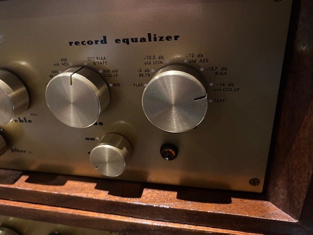
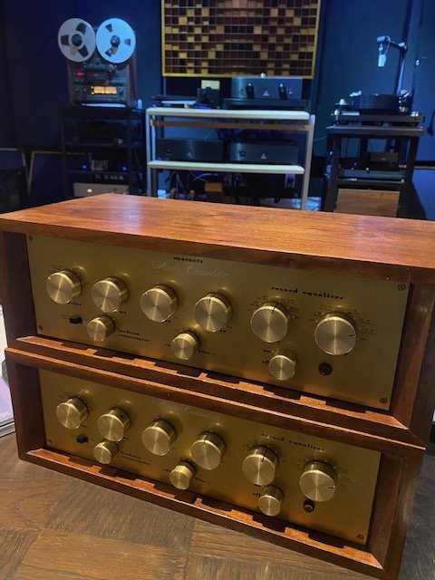
Agreed. Or buy a second hand phono pre (such as yours, or a new one !) to modify. I have not tried modifying active RIAA set ups, but I guess it just takes some experimentation to get an accurate response. A Marantz 7 would be quite intriguing.... How does it sound ?Hi Adrian, I really see no difference in difficulty. All my previous ones had passive networks, but I just modified the Marantz 7 with a feedback network, and it was just as easy. I just did it for an educational Youtube video, not expecting any miracle but the result exceeded my expectations.
If one knows what he is doing, he can put together a very, very, very good head pream for just $250 in parts.
A dream came true - R2R.
- Thread starter byrdparis
- Start date
You are using an out of date browser. It may not display this or other websites correctly.
You should upgrade or use an alternative browser.
You should upgrade or use an alternative browser.
It is not hard, easier than it might look at the first glance, and the sound is surprisingly good. I still need to give it more listening vis-a-vis the more serious contenders, but it is certainly better than what you find inside the machines I know.
GO VICTOR. A number of the older tube stereo preamps (and probably mono) also had a switchable input for tape heads. All this position had to do was supply the correct equalization - which was/is far from rocket science.Hi Adrian, I really see no difference in difficulty. All my previous ones had passive networks, but I just modified the Marantz 7 with a feedback network, and it was just as easy. I just did it for an educational Youtube video, not expecting any miracle but the result exceeded my expectations.
If one knows what he is doing, he can put together a very, very, very good head pream for just $250 in parts.
As I remember, The Marantz 7 even had a variable pot on the back to "correct" for HF response, when in the tape head position. I have heard from a few other folks who have had excellent (sounding) results form the 7. AND WHY NOT - it was a wonderful design!!!!
The Marantz 7 has gain pots in the back that will affect the eq. I have used it and it sounds quite good. I believe it is set for NAB eqGO VICTOR. A number of the older tube stereo preamps (and probably mono) also had a switchable input for tape heads. All this position had to do was supply the correct equalization - which was/is far from rocket science.
As I remember, The Marantz 7 even had a variable pot on the back to "correct" for HF response, when in the tape head position. I have heard from a few other folks who have had excellent (sounding) results form the 7. AND WHY NOT - it was a wonderful design!!!!
I prefer the Model 1 Consolettes though!
Attachments
Last edited:
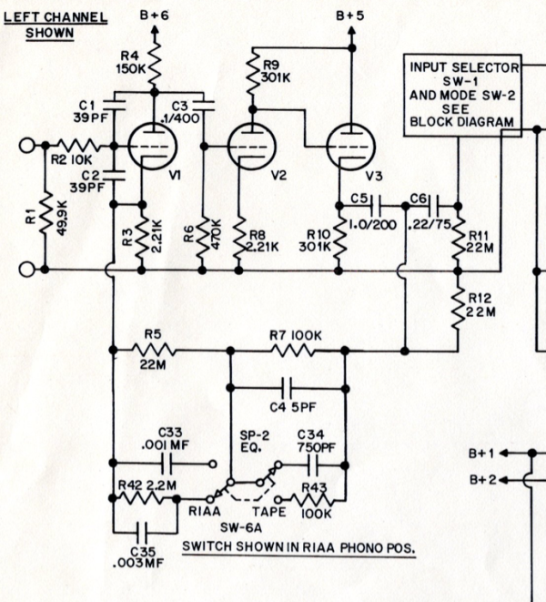
Yes, I studied the Marantz schematics and it has various phono EQs as well as NAB for tape head. As the LF pole for RIAA is almost identical to that of NAB, it is just a matter of bypassing the rest of the RIAA EQ components with the pot (it has a 15K pot in series with a 5K resistor).The Marantz 7 has gain pots in the back that will affect the eq. I have used it and it sounds quite good. I believe it is set for NAB eq
I prefer the Model 1 Consolettes though!
I bought the board from Taobao, the Chinese equivalent of AliExpress, and also a pre-drilled chassis and transformers for the HT and filaments. I also needed to buy the 6X4 rectifier as I only have 6CA4 in my stash, which uses a different base. The whole thing came to around RMB1100, which is around US$155. I still have to get a couple of 20K pots, and change the first interstage coupling caps to a larger value as suggested by Victor. I am going to compare it with the internal Audvance output board I am using with my B77 now.
Just as clarification - the board sold today on ebay is based on the Marantz 7 circuit, and I have seen slightly different physical constructions. It has no provision for multiple EQ's, but that can easily be added externally to it.
The basic circuit has been time-tested, and AFAIK it is still used today in some high-end products.
It is probably also interesting to note that the very popular and respected EAR 834 circuit is very similar, except it applies the feedback differently.
Be it all as it may, it is a very convenient vehicle for learning and experimentation and if done right, will produce very good results, exceeding what one would normally expect at such moderate cost.
I am planning a test comparing it to some far more expensive alternatives.
Hello,Yes, I studied the Marantz schematics and it has various phono EQs as well as NAB for tape head. As the LF pole for RIAA is almost identical to that of NAB, it is just a matter of bypassing the rest of the RIAA EQ components with the pot (it has a 15K pot in series with a 5K resistor).
I bought the board from Taobao, the Chinese equivalent of AliExpress, and also a pre-drilled chassis and transformers for the HT and filaments. I also needed to buy the 6X4 rectifier as I only have 6CA4 in my stash, which uses a different base. The whole thing came to around RMB1100, which is around US$155. I still have to get a couple of 20K pots, and change the first interstage coupling caps to a larger value as suggested by Victor. I am going to compare it with the internal Audvance output board I am using with my B77 now.
Is there a schematic you can share for the Marantz and/or for your project?
Thank you
I understand the Kondo M7 is also based on the Marantz circuit (hence the moniker).Just as clarification - the board sold today on ebay is based on the Marantz 7 circuit, and I have seen slightly different physical constructions. It has no provision for multiple EQ's, but that can easily be added externally to it.
The basic circuit has been time-tested, and AFAIK it is still used today in some high-end products.
It is probably also interesting to note that the very popular and respected EAR 834 circuit is very similar, except it applies the feedback differently.
Be it all as it may, it is a very convenient vehicle for learning and experimentation and if done right, will produce very good results, exceeding what one would normally expect at such moderate cost.
I am planning a test comparing it to some far more expensive alternatives.
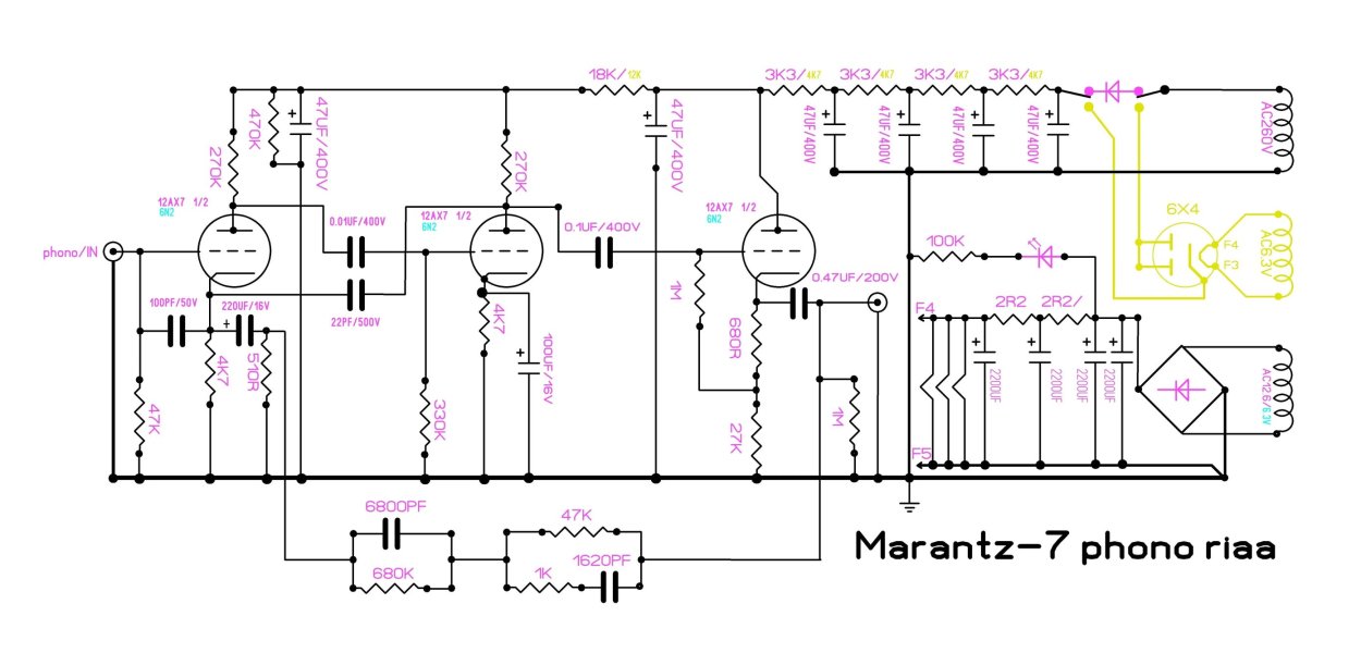
Back to the Chinese phono board. I notice the cap in the LF section of the RIAA feedback circuit is 6800pF. On the original Marantz schematic, it is 5600pF. The original network gives a LF time constant of 3808 uS, which is almost exactly the official RIAA (and NAB) standard, whereas the network on this board gives a tc of 4624 uS, which will lower the corner frequency of the low pass to 34Hz. I wonder why ? I will start with the board as is, but likely will need to change the cap back to 5600pF.
Since I was trying to achieve the IEC EQ curve, any pole would be detrimental. Moving it from 50 Hz to lower frequency would be nice, by increasing the value of the 680K resistor. At first I wanted to go to about 1.5 Meg, but then a friend suggested removing it entirely.
At first I had some reservations about such a step, as it would make you rely on some unspecified parameters, a definite no-no for any serious design, but eventually I did that and it worked just fine. If you would like to be more conservative, then going with something like 2.2 Meg might be a good alternative, as it would place the pole below the audible range.
There are basically two ways of reducing that pole's frequency - by increasing the value of either the capacitor or the resistor.
Increasing the capacitance will work, but it will also reduce the middle frequency gain, which is not desirable here, so my strong preference is for changing the resistor.
So specifically, are we removing the 1K and 1620pf RIAA network components and replacing the 47K resistor for the shelf by a trim pot of a value of 10k and adjusted for response.?Here is the schematic for the board I bought, and as far as more details, they are mostly covered in my 3-part video:
View attachment 136600
If this detail was provided in the video I missed it.
Thank you!
take a look at the tube head amp circuit of old tube amplifiers like sansui. maybe interesting for you.
Here is the schematic for the board I bought, and as far as more details, they are mostly covered in my 3-part video:
View attachment 136600
Marantz ADDED a third, cathode follower (CF) stage to the two-stage amplification circuits used by most manufacturers heretofore. "Better sound" was achieved by driving the active equalization feedback network (back to the first stage) from the lower output impedance created by the added CF stage. Don't remember technically why this is better - someone else feel free to chime in. Using a lower (more modern) Rp tube like a 6DJ8 for the third stage instead of an AX7 might even yield a slight improvement.Here is the schematic for the board I bought, and as far as more details, they are mostly covered in my 3-part video:
View attachment 136600
The 6DJ8 family tube (I mostly use the 6922's) would indeed work better in that regard (that's why I love them), BUT at a substantial gain reduction - its gain is just about 30, vs. up to 100 for the 12AX7. Feeding the EQ circuit from the lower output resistance node minimizes the frequency response variation due to its reactive nature.
On top of that making it work from the same plate supply as the 12AX7 would be impractical, due to their different needs. And using the 6922's for both stages would reduce the gain even more.
Overall the subject configuration is effective, no wonder it is so widely used.
On top of that making it work from the same plate supply as the 12AX7 would be impractical, due to their different needs. And using the 6922's for both stages would reduce the gain even more.
Overall the subject configuration is effective, no wonder it is so widely used.
I prefer the 12AT7 to the 6DJ8 as you can run some current on it (unlike the 12AX7) and you get far better bandwidth (than a 12AX7) since less troubles with stray capacitance.
6DJ8s, 6922 and similar, tend to have more troubles with microphonics as they were not intended for audio. If you change the impedance at the output with a different tube the amount of feedback being presented will be altered.
6DJ8s, 6922 and similar, tend to have more troubles with microphonics as they were not intended for audio. If you change the impedance at the output with a different tube the amount of feedback being presented will be altered.
@stellavox was suggesting a 6dj8 for the third tube, the cathode follower, where there would be no loss of gain since the CF is essentially unity gain regardless of tube. I haven’t tried a 6dj8 as a CF but in general I don’t like its sound; for that matter I prefer using tubes where I don’t need a CF. @Foxbat agrees with that since he said so in his video.The 6DJ8 family tube (I mostly use the 6922's) would indeed work better in that regard (that's why I love them), BUT at a substantial gain reduction - its gain is just about 30, vs. up to 100 for the 12AX7. Feeding the EQ circuit from the lower output resistance node minimizes the frequency response variation due to its reactive nature.
On top of that making it work from the same plate supply as the 12AX7 would be impractical, due to their different needs. And using the 6922's for both stages would reduce the gain even more.
Overall the subject configuration is effective, no wonder it is so widely used.
Similar threads
- Replies
- 2
- Views
- 232
- Replies
- 4
- Views
- 290
- Replies
- 3
- Views
- 613
- Replies
- 7
- Views
- 308
| Steve Williams Site Founder | Site Owner | Administrator | Ron Resnick Site Owner | Administrator | Julian (The Fixer) Website Build | Marketing Managersing |


