ack's system - end of round 1
- Thread starter ack
- Start date
You are using an out of date browser. It may not display this or other websites correctly.
You should upgrade or use an alternative browser.
You should upgrade or use an alternative browser.
That's very interesting - I've never come across hot capacitors before in all my long experience with mains frequency rectified supplies. Which inclines me to think maybe the capacitors themselves aren't pukka ones. Could be that although the 3900uF is marked 16V it isn't really, its something lower. But if it was over-voltage then you'd see the metal top of the can start to bow outwards as internal pressure builds up. No evidence of that right? If the capacitor really is heating up purely due to ripple current that current is going to have to be very large. Let's take a look at a spec sheet for similar capacitors to yours - I'll get back to this post when I've done that.
Yes, the top plates have not buckled or anything, nor are there leaks; but the electrolyte may have partly dried out. And yes, I also think there is quite a bit of ripple current going through, as I said earlier. It was this heat issue that made me launch on mods, because I would either mod it or sell it, lest these caps shorted out and blew out the whole thing, given that I also byass the fuse. And sonically, I can tell you, as Al wrote a while ago, it's a knock-out, especially with dynamics. A very well executed DAC, now that it's fixed
That would be normal in such a product yes. But strangely the supplies are not symmetrical - one is double the other. Usually analog supplies are symmetric - equal in positive and negative. So the plot thickens....
Yeah not sure what the Berkeley folks are doing, but again, it's beautiful stuff; perhaps one of the supplies is dedicated to support functions, like the display and control circuit???!?! Cannot tell w/o a schematic. But I can say with conviction that I have not stopped listening to digital over and over again for a month now. It is really impressive, and the output section capacitor change is also part of this.
The long wires are twisted, so low inductance hence less chance for resonance at PSU freqs. Besides the caps got hot before those wires were installed, they're the solution to the heating problem.
Precisely, you are reading me right
Ah, I missed that you had heat prior. Long wires always increase resonation possibilities, twisted or not.
In digital circuits it's likely the 12v is used for regulated 3.3 &5v , and perhaps screens etc. The higher voltage being for analog output, particularly high voltage balanced.
The whole thing may run cooler by correcting what I'd call common place mistakes in the AC section. There's numerous changes I would make, really.
Regarding the Panasonic specs that opus111 brought up, I think this is the 3900uF/16VDC one http://www.mouser.com/ProductDetail...=sGAEpiMZZMtZ1n0r9vR22ThEfR5lzZmmqdtSX4Jqx30=
Yes, the top plates have not buckled or anything, nor are there leaks; but the electrolyte may have partly dried out.
Good, so we can rule that out. Running caps hot isn't necessarily a problem, it depends on the precise application, it does definitely shorten their life. But ESRs are much lower in a hot cap so there's an upside, however in this position there's practically no advantage to having low ESR really.
And yes, I also think there is quite a bit of ripple current going through
Its something amenable to being modelled in LTSpice, so I'll get on to it in due course when I've found a representative datasheet for the caps you've pulled. Do they have brand identification markings? I couldn't see any sign of manufacturer on the pic you're showing.
as I said earlier. It was this heat issue that made me launch on mods, because I would either mod it or sell it, lest these caps shorted out and blew out the whole thing, given that I also byass the fuse. And sonically, I can tell you, as Al wrote a while ago, it's a knock-out, especially with dynamics. A very well executed DAC, now that it's fixed
The Berkeley guys know what they're doing in general in regards noise control. The PCB layouts are top-notch in terms of isolation and grounding. Those rather prehistoric looking transformers are there for a purpose - whereas the fashion designers use toroids these boys understand their weaknesses and avoid them. But seems they still have one or two blindspots we can address...
<edit> Thanks for the cap details link.
Boy, do they know what they are doing! You can say that again. I have no problem with the transformers, apart from lack of magnetic field isolation - hence the two strips of mumetal running in parallel to each other, as you can see between the PS and main board, on the left - they are bridged with electrical tape (don't ask why). You can also spot the computer fan I installed, touching the wire connecting to C7.
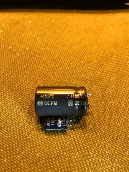
The caps are definitely Panasonic FM, they have the "M" symbol and FM marking.
Prehistoric? Hmm.. I generally prefer dual bobbins. They have less noise compared to toroids that lack a shield.
You got to admit though the Y-cap to hot is... well it's taboo for a reason.
You got to admit though the Y-cap to hot is... well it's taboo for a reason.
The caps are definitely Panasonic FM, they have the "M" symbol and FM marking.
I've pulled up the DS and your caps have the largest can size which is 16mm by 25mm. The ripple current rating being related to can size, its 3.8A but only at 100kHz. Since yours is a full-wave rectifier circuit the ripple current is at 120Hz which needs a 0.8 multiplier applied. So we have 3.8 * 0.8 = 3A for the maximum allowed ripple.
Now since the trafo's only 12VA a 3A ripple current wouldn't be able to flow from a 10V winding without substantial heating in the transformer. But the trafo's running fairly cool?
Prehistoric?
Suggest polishing up your listening skills. Notice I wrote 'prehistoric looking'.
Hmm.. I generally prefer dual bobbins. They have less noise compared to toroids that lack a shield.
They let less noise pass than toroids, yes. Which is a very good reason for choosing them. But they just don't look as sexy as nicely potted toroids.
I've pulled up the DS and your caps have the largest can size which is 16mm by 25mm. The ripple current rating being related to can size, its 3.8A but only at 100kHz. Since yours is a full-wave rectifier circuit the ripple current is at 120Hz which needs a 0.8 multiplier applied. So we have 3.8 * 0.8 = 3A for the maximum allowed ripple.
Now since the trafo's only 12VA a 3A ripple current wouldn't be able to flow from a 10V winding without substantial heating in the transformer. But the trafo's running fairly cool?
The transformers are warm, I could call them fairly cool, certainly compared to anything else around there.
Back of the envelope calculation here, working backwards from the transformer's rating (12VA).
Since we have two windings let's assume they're equally divided in wattage, so 6W each. On the lower voltage one (10V) that's 600mA.
For 600mA output current the charging current (assuming diodes conduct 15% of the time) is theoretically 4A peak. But it'll not reach this due to the resistance of the trafo winding, a regulation figure of 20% or so isn't uncommon on small trafos. I can't get the RMS ripple current anywhere near 3A in this scenario.
Still very much a mystery how those caps could be getting so hot.
Indeed. They might have been bad, as you said; but from the get-go?????? and both of them? I think we are missing something
Definitely there's a very important thing we're missing as the pieces aren't fitting together at all well at the moment!
Added to this - if there really were a 600mA current from the C7-smoothed supply your regulator and the trafo would be getting much warmer than they are. In your present set-up you've much bigger caps at the ends of those twisted pairs which would make for an even hotter trafo than when the original caps were in position. Simply because bigger-valued caps mean bigger currents flowing.
Added to this - if there really were a 600mA current from the C7-smoothed supply your regulator and the trafo would be getting much warmer than they are. In your present set-up you've much bigger caps at the ends of those twisted pairs which would make for an even hotter trafo than when the original caps were in position. Simply because bigger-valued caps mean bigger currents flowing.
ack, can you post the pics of your REL after all the mods you've done to it, please? Just curious what it looks like...Fun stuff Steve; and here's some more...
On the REL mods: I mentioned there are three electrolytics in the bass summation/amplification circuit that I didn't like, and these Daewoo have now been replaced with much higher quality Nichicon (10% tolerance). I have never heard such tight bass from the sub. I don't know if I am done yet, but I am probably done with REL subs going forward.
Oh, and BTW, did you replace the stock wire connecting Neutrik input jack to PCB?
ack,
this has been a lot of fun to follow...there are 2 mods i have always thought about. The first is upgrading the clock in my Zanden which Audiocrack has had done. The second is based o your own adventures here with the REL. By any chance, do you have any views on Velodyne's DD18+? I suppose you'd need to look inside but just thought i would ask, since i am the last person who should open up anything electronic.
this has been a lot of fun to follow...there are 2 mods i have always thought about. The first is upgrading the clock in my Zanden which Audiocrack has had done. The second is based o your own adventures here with the REL. By any chance, do you have any views on Velodyne's DD18+? I suppose you'd need to look inside but just thought i would ask, since i am the last person who should open up anything electronic.
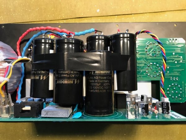
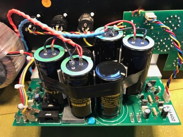
Here are the pictures; I ended up installing a total of 6x10,000uF PS caps (5 are clearly seen, the last is sort of hidden, facing down in the back), plus the three black Nichicon seen on the right hand side. The two PS Mundorf facing down were secured to the board in order to withstand the additional weight of the other four. The caps are attached to each other with two-sided tape plus the electrical tape. I have not replaced any cables.
Lloyd, sorry I can't speak of the Velodyne without looking at the board.


Lloyd, sorry I can't speak of the Velodyne without looking at the board.


Hi Ack,
Thanks and thought as much. Perfectly understand and honestly, if i were to have a techie open it up to take a look...he probably would end up the one sourcing and replacing/upgrading parts. Nice photos...sounds like a great upgrade thanks to your knowledge and skills.
Thanks and thought as much. Perfectly understand and honestly, if i were to have a techie open it up to take a look...he probably would end up the one sourcing and replacing/upgrading parts. Nice photos...sounds like a great upgrade thanks to your knowledge and skills.
Impressive coupling of topology changes with perceived sonic/aural shifts. Some great research and development...remarkable. Congrats.
Thank you and sorry for the delayed response, but I frequently miss some posts.
You CAN'T be done with REL subs. You need to mod mine.
Missed this one too. Glad to help if I can! So here's a thought: why not get Magico subs
Similar threads
- Replies
- 21
- Views
- 13K
| Steve Williams Site Founder | Site Owner | Administrator | Ron Resnick Site Owner | Administrator | Julian (The Fixer) Website Build | Marketing Managersing |


