
Mine is only slightly less neat ;-) Point to point construction makes it easy to modify the circuit.Like this sounds damn good.
Pre phono 3 - MM-MC Analogic Phonografic Preamplification System "APPS" by B. Aloia
www.audiodesignguide.com


Phono Stage and XLRs
- Thread starter jadis
- Start date
You are using an out of date browser. It may not display this or other websites correctly.
You should upgrade or use an alternative browser.
You should upgrade or use an alternative browser.
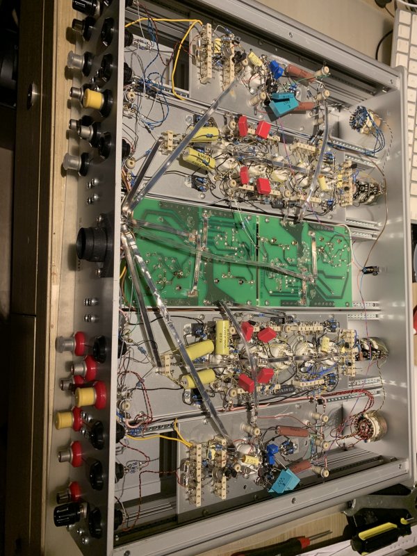
Looks like vacuum state ...great.Mine is only slightly less neat ;-) Point to point construction makes it easy to modify the circuit.
Of course ,diy must be point to point
")

Yes, a prototype developed with Allen.Looks like vacuum state ...grear.
Of course ,diy must be point to point
Jim, I have to straighten you out on this bit. Cartridges and any floating inductive source like a tape head or dynamic microphone are ideal balanced sources. The cartridge outputs are pins 2 and 3 of the XLR as you know and the shield (the tonearm ground) is pin 1.Cartridges are not balanced, they are floating. A balanced connection requires 3 wires, not 2, hence XLR connectors.
In order to be balanced, both output polarities (+ and -) need to have the same impedance to common mode ground (this happens in phonostage). Connecting pins 1 and 3 together destroys common mode noise rejection. Pin 1 does act as a nice shield if only connected on the RX end, but you still do not have balanced drive. If impedances are not matched and you do not get CM rejection.
There are two ways to make a balanced phono connection:
1) Use a pair of 23.5k resistors to ground for each cartridge terminal. Thus, you get balanced drive and a 47k differential loading.
2) Use a step-up transformer with center tap on input. Connect center tap to ground. Bingo!
jh
We've been doing balanced line phono sections since 1989. We use your option 1) above for input. Our phono sections are balanced from input to output and passively equalized with the EQ in the differential domain.
The cartridge being a balanced source is is why if RCA connections are used, a grounding wire is used that no other single-ended source seems to need; when going from balanced to single-ended without a transformer, using a ground wire for the shield connection is the best way to do it.
So if the tonearm has a 5 pin connector as an output, the ground connection becomes the shield connection of the tonearm cable and is pin 1 of the XLRs of both channels. If the tonearm has RCA outputs and a ground post, then the tonearm cable has RCA inputs, but neither RCA uses the shield, which is instead tied to the ground post. At the other end, the XLRs are wired in the same manner as the tonearm cable with the 5 pin DIN.
In a balanced connection, ideally ground is ignored, which is to say it never (or should never) carry any signal. A tonearm is a good example of how this works. When the ground is part of the signal return circuit, it opens the system to ground loops. This is part of the reason balanced operation is done the way it is.
Using a center tap is not a good idea with any balanced connection since the center tap cannot be perfectly placed. Therefore it degrades the Common Mode Rejection Ratio. Better to simply have it float. IOW to use an SUT, pins 2 and 3 of the XLR are the transformer connection and pin 1 is the case of the transformer or transformer box (as well as the case of the transformer, if external to the preamp). The output can be either balanced or single-ended depending on whether one side of the output is grounded or not (the transformer doesn't care). If the output is single-ended, you still get the CMRR that the transformer has (which is usually very good) at its input.
Quoting from Wikipedia:Jim, I have to straighten you out on this bit. Cartridges and any floating inductive source like a tape head or dynamic microphone are ideal balanced sources. The cartridge outputs are pins 2 and 3 of the XLR as you know and the shield (the tonearm ground) is pin 1.
In telecommunications and professional audio, a balanced line or balanced signal pair is an electrical circuit consisting of two conductors of the same type, both of which have equal impedances along their lengths, to ground, and to other circuits.
Question for you: what does the differential signal from the cartridge have to do with the tonearm ground? What is the impedance there?
Thanks for the answer.
P.S. Differential signalling is a method for electrically transmitting information using two complementary signals. The technique sends the same electrical signal as a differential pair of signals, each in its own conductor. The pair of conductors can be wires in a twisted-pair or ribbon cable or traces on a printed circuit board.

A signal transmitted differentially. Notice the increased amplitude at the receiving end.
Last edited:
To your first question: Very little. The impedance is very high (air dielectric), and equal on either side of the signal. The receiving circuit may need some kind of resistance to ground on either input; if so those resistances should be matched for best CMRR. If the input is a transformer of course then the impedance to ground at either input is very high, nearly as that of the tonearm output.Quoting from Wikipedia:
In telecommunications and professional audio, a balanced line or balanced signal pair is an electrical circuit consisting of two conductors of the same type, both of which have equal impedances along their lengths, to ground, and to other circuits.
Question for you: what does the differential signal from the cartridge have to do with the tonearm ground? What is the impedance there?
Thanks for the answer.
P.S. Differential signalling is a method for electrically transmitting information using two complementary signals. The technique sends the same electrical signal as a differential pair of signals, each in its own conductor. The pair of conductors can be wires in a twisted-pair or ribbon cable or traces on a printed circuit board.
View attachment 119442
A signal transmitted differentially. Notice the increased amplitude at the receiving end.
If the last sentence is from a Wiki page, please be informed it is misleading. If you take the example of a phono cartridge, by sending the signal balanced or single ended, the amplitude does not change. If both sides of the signal are applied to a balanced input and amplified, the output amplitude cannot be known without knowing the topology of the circuit and its gain. Now if we assume an opamp with fixed gain and compare both inputs driven to only one input driven (with the 2nd input at ground along with the output of the cartridge on that side) then the amplitude at the output will be the same.
It's not the Wiki that's misleading, it's that someone misled you and you're now misleading others.To your first question: Very little. The impedance is very high (air dielectric), and equal on either side of the signal. The receiving circuit may need some kind of resistance to ground on either input; if so those resistances should be matched for best CMRR. If the input is a transformer of course then the impedance to ground at either input is very high, nearly as that of the tonearm output.
If the last sentence is from a Wiki page, please be informed it is misleading. If you take the example of a phono cartridge, by sending the signal balanced or single ended, the amplitude does not change. If both sides of the signal are applied to a balanced input and amplified, the output amplitude cannot be known without knowing the topology of the circuit and its gain. Now if we assume an opamp with fixed gain and compare both inputs driven to only one input driven (with the 2nd input at ground along with the output of the cartridge on that side) then the amplitude at the output will be the same.
You should immediately patent the air dielectric as a signal source.
I'm afraid to ask if you can imagine what the oscilloscope will show when a signal from this source is applied to its input.
I'm not misleading anyone. You can measure this stuff very easily and its very repeatable. Its a common myth that when you go from single-ended to balanced you get a 6dB increase in signal level. That only happens when the balanced standard (AES48) is not being observed at the output of an active circuit driving a balanced line.It's not the Wiki that's misleading, it's that someone misled you and you're now misleading others.
You should immediately patent the air dielectric as a signal source.
I'm afraid to ask if you can imagine what the oscilloscope will show when a signal from this source is applied to its input.
Dielectrics can cause noise but are not signal sources otherwise. Keeping noise down is part of why higher quality dielectrics are used in good quality coupling capacitors and also as insulation in interconnect cables.
No need for fear- most 'scopes have single-ended inputs so a cartridge presents the 'scope with an audio signal of low level depending entire on what LP is being played. Done it many times.
FWIW, we were the first to offer a balanced line phono stage and a line of balanced line products for home stereo use.
Air dielectric is actually a thing; if you have ever seen those three wires on actual telephone poles in the country, they were spaced in such a way that the air dielectric caused the resulting transmission line to have a characteristic impedance of 600 Ohms. It was the phone company that actually started using balanced lines first because they made trans- and inter-continental phone calls possible due to greater intelligibility. So 600 Ohms became the standard termination impedance used with balanced lines in the studio back in the tube era. The venerable Ampex 351 tape electronics was designed to drive 600 Ohms and had a termination switch for the output transformer in case it was not driving such a load, so as to prevent ringing in the transformer.
I think the basis of your confidence is faith, not knowledge. That's why Wiki is lying, even though there is information from textbooks.I'm not misleading anyone. You can measure this stuff very easily and its very repeatable. Its a common myth that when you go from single-ended to balanced you get a 6dB increase in signal level. That only happens when the balanced standard (AES48) is not being observed at the output of an active circuit driving a balanced line.
We have a saying: if you think you have made a discovery, read the textbook.
I think the basis of your confidence is faith, not knowledge. That's why Wiki is lying, even though there is information from textbooks.
We have a saying: if you think you have made a discovery, read the textbook.
I did not saying Wiki is lying. I said there was something misleading. Look at my prior explanation as to why. If you've worked with inductive devices like cartridges, tape heads and coupling transformers you'd realize immediately that they don't care whether one side is grounded or not -their output voltage does not change.
Or you could assume that it does, somehow violating Kirchoff's Law, thus creating a new branch of physics and solving the world's energy problems.
very well explained. Equivalent circuit diagram for a capacitor.I'm not misleading anyone. You can measure this stuff very easily and its very repeatable. Its a common myth that when you go from single-ended to balanced you get a 6dB increase in signal level. That only happens when the balanced standard (AES48) is not being observed at the output of an active circuit driving a balanced line.
Dielectrics can cause noise but are not signal sources otherwise. Keeping noise down is part of why higher quality dielectrics are used in good quality coupling capacitors and also as insulation in interconnect cables.
No need for fear- most 'scopes have single-ended inputs so a cartridge presents the 'scope with an audio signal of low level depending entire on what LP is being played. Done it many times.
FWIW, we were the first to offer a balanced line phono stage and a line of balanced line products for home stereo use.
Air dielectric is actually a thing; if you have ever seen those three wires on actual telephone poles in the country, they were spaced in such a way that the air dielectric caused the resulting transmission line to have a characteristic impedance of 600 Ohms. It was the phone company that actually started using balanced lines first because they made trans- and inter-continental phone calls possible due to greater intelligibility. So 600 Ohms became the standard termination impedance used with balanced lines in the studio back in the tube era. The venerable Ampex 351 tape electronics was designed to drive 600 Ohms and had a termination switch for the output transformer in case it was not driving such a load, so as to prevent ringing in the transformer.

Rp are resistors, the polarization shift occurs in the dielectric of the capacitor. When the capacitor is charged and discharged at high levels, an air gap is created between the plates. These are oil-filled capacitors at an advantage because they prevent air gaps. e.g. mundorf silver in oil or other brands. Telefunken does 600ohm symmetrical too, in studio technology with the V series since 1954.

Thats highend from the past and today too, microphone preamp that you use tapehead amp or phono amp with some mods.
Is it possible to mislead when you tell the truth? I believe that misleading and lying are synonymous.I did not saying Wiki is lying. I said there was something misleading. Look at my prior explanation as to why. If you've worked with inductive devices like cartridges, tape heads and coupling transformers you'd realize immediately that they don't care whether one side is grounded or not -their output voltage does not change.
Or you could assume that it does, somehow violating Kirchoff's Law, thus creating a new branch of physics and solving the world's energy problems.
I worked and now work with cartridges, tape heads and coupling transformers, so I can't understand why you consider cartridges and tape heads balanced signal sources? I have never seen these devices with three pins. In Studer tape recorders, for example, the signal is amplified in unbalanced form, and for balanced output, the unbalanced output signal is simply inverted and added to the unbalanced signal.
This is a technically rational and correct solution not only for tape recorders, but also for RIAA preamps.
Is the dielectric releasing air?When the capacitor is charged and discharged at high levels, an air gap is created between the plates.
As Jim Hagerman said, a cartridge output is floating, not balanced. The very word “balanced” tells the story—something can only be balanced with respect to something else, and for a cartridge output that necessarily means a third pole.
No they breathe...Is the dielectric releasing air?

If you apply a voltage to the plates of the capacitor then the dipoles of the dielectric align with their poles. These dipoles are twisted due to undefined polarization caused by a charge on the plates. good manufacturers specify this angle (tangent loss angle). If the capacitors are defective (leakage), the resistance (high ESR) increases. If the charge is high, the plates are pulled towards each other. If the capacitor is discharged, they move away and the capacitor breathes. In order to reduce breathing, oil is often used at expensive capacitor so that the capacitor has a stable nominal value and tolerance complies. I hope it was understandable.
P.S
The electric charge is measured in coulombs, you would be surprised how much newton force acts on such a small capacitor. there are quickly 200 newtons.
I have a question: what does this capacitor have to do with the cartridge winding? or to the magnetic head?If you apply a voltage to the plates of the capacitor then the dipoles of the dielectric align with their poles. These dipoles are twisted due to undefined polarization caused by a charge on the plates. good manufacturers specify this angle (tangent loss angle). If the capacitors are defective (leakage), the resistance (high ESR) increases. If the charge is high, the plates are pulled towards each other. If the capacitor is discharged, they move away and the capacitor breathes. In order to reduce breathing, oil is often used at expensive capacitor so that the capacitor has a stable nominal value and tolerance complies. I hope it was understandable.
Belief and knowing are two different things, as you pointed out earlier. Wiki pages are often created by the public, and its possible for them to be misinformed with no intention of lying and thus be misleading.Is it possible to mislead when you tell the truth? I believe that misleading and lying are synonymous.
I worked and now work with cartridges, tape heads and coupling transformers, so I can't understand why you consider cartridges and tape heads balanced signal sources? I have never seen these devices with three pins. In Studer tape recorders, for example, the signal is amplified in unbalanced form, and for balanced output, the unbalanced output signal is simply inverted and added to the unbalanced signal.
This is a technically rational and correct solution not only for tape recorders, but also for RIAA preamps.
You don't need a center tap on a tape head or cartridge for it to be a balanced source. As I explained earlier, a center tap can't be perfectly placed- and so would degrade the CMRR. That lesson was hard a hard one in the early days of balanced operation. You don't want ground referenced by the source anyway- this prevents ground loops from causing hum and noise. My U67 mics employ multiple windings at their output so to drive different load impedances, but there's no center tap.
Jensen Transformers is a very respected manufacturer of microphone input transformers. Take a look. No center tap.
When you have a single-ended output applied to pin 2 of the XLR, and simply use an inverted signal for pin 3, if either references ground, you can introduce a ground loop. So in a solid state embodiment, the best way to drive a balanced line sans output transformer is with a balanced line driver. This sort of IC was not available when many of the Studers were built. Tascam had a similar practice of simply inverting a single-ended output signal with their home studio products back in the 1970s. While that does produce a balanced output, its not ideal. This is why output transformers are still in common use in solid state studio products, because they are immune to ground loops due to their isolation and can provide very good CMRR values.
That a center tap is needed for balanced operation is one of the bigger myths around the topic. I know that this can be difficult to accept- myths often experience a difficult death.
This is not a myth, it is a definition of a balanced way of transmitting information. And Wiki is not lying here, mistakes are corrected there very quickly. This is a public resource.That a center tap is needed for balanced operation is one of the bigger myths around the topic. I know that this can be difficult to accept- myths often experience a difficult death.
Also, look in the radio engineering textbooks, it's not a wiki, no one is being misled there.
The name "balanced" is widely promoted by marketers, it improves sales, because the absolute majority of consumers do not understand what it is, but it is called beautiful.
If you need a center tap for balanced operation, please explain why Jensen and Neumann, both highly respected in their fields, omitted it. This is not rhetorical; I'm interested in what you are able to find from these manufacturers.This is not a myth, it is a definition of a balanced way of transmitting information. And Wiki is not lying here, mistakes are corrected there very quickly. This is a public resource.
Also, look in the radio engineering textbooks, it's not a wiki, no one is being misled there.
Bill Whitlock wrote a book while working at Jensen. On Page 8 is where it gets germane; also look at page 15. The idea that a center tap is needed isn't given much consideration...
At this point I've proven that a center tap isn't needed. That means that the idea that it is needed is simply a myth.
I don't need a center tap, I don't use balanced signals.If you need a center tap for balanced operation, please explain why Jensen and Neumann, both highly respected in their fields, omitted it. This is not rhetorical; I'm interested in what you are able to find from these manufacturers.
Bill Whitlock wrote a book while working at Jensen. On Page 8 is where it gets germane; also look at page 15. The idea that a center tap is needed isn't given much consideration...
At this point I've proven that a center tap isn't needed. That means that the idea that it is needed is simply a myth.
First, it is a PP signal with a corresponding sound signature. I like the SE sound better.
Secondly, for home use, the protection against interference provided by RCA cables is quite sufficient.
In my opinion, there are only two rational uses of balanced signals: the input of a PP amplifier and the output of a delta-sigma DAC.
We are all human and can make mistakes, you and your authorities are no exception.
Similar threads
- Replies
- 52
- Views
- 5K
- Replies
- 3
- Views
- 959
| Steve Williams Site Founder | Site Owner | Administrator | Ron Resnick Site Owner | Administrator | Julian (The Fixer) Website Build | Marketing Managersing |