Hello Members,
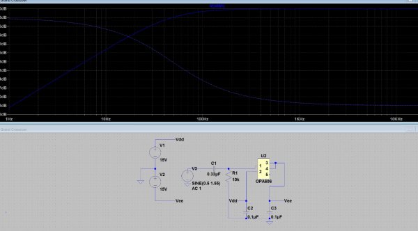
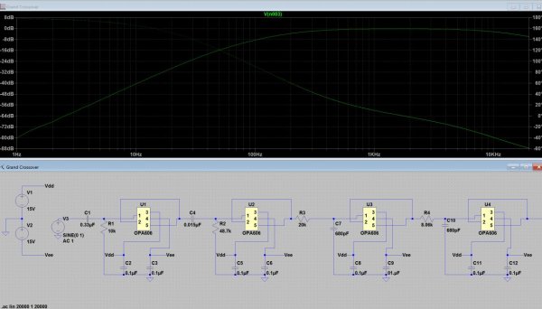
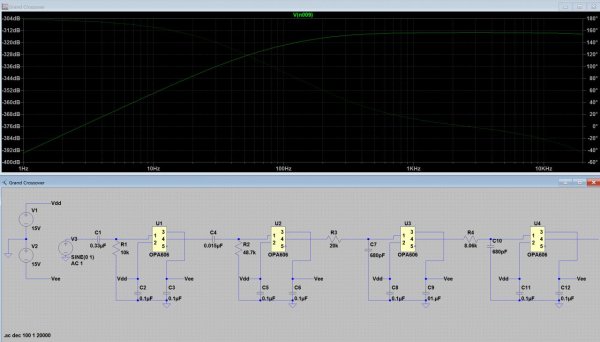
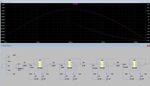
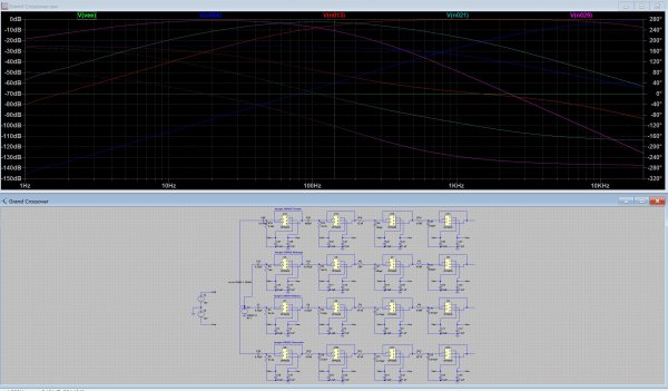
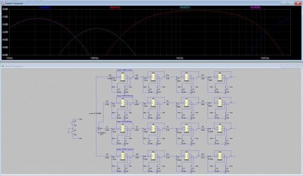
i am trying to find a software which can simulate the crossover schematic.
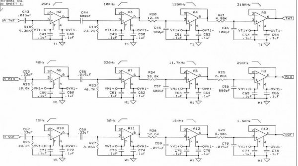
I did check the values on the schematics in various calculators and they seem to check out.
From what i understand, they are two 1st order high pass filters in series + two 1st order low pass filters in series to create a real slope.
Q: Is this a bandpass filter or how do you call that?
Q: Are the crossover points at 0db or -6? (For example: 0db @ 48Hz ; -6db @96Hz)
Thanks for any help
Florian


