Symmetrical Crossovers - Why? - Advantage/Disadvantage

The audio output is AC. A battery delivers DC. A power supply ideally delivers DC but always has a small amount of AC noise and ripple.

I use pencil and paper, Mathcad, and Matlab for crossover (filter) analysis but there are dedicated programs to make life easier for speaker designers. I have almost zero experience with the dedicated programs so am not competent to comment.
 
Quote from another review of Gauder Akustik:

" .... The crossover design is also somewhat unusual, with slopes of more than 50 dB/Octave, something few would ever dare to attempt. Thus the individual drivers in the transition region have little overlap, which results a more focused center image and the sonic approximation of a point source.

The basic idea of a symmetrical architecture, as implemented in the Berlina series, was transferred to the Arcona 100. By using the same components on the plus and minus side, the rear motion of speaker is better damped and the amplifier is presented with a more balanced load. ..."

So, do the above statements hold true or are there other factors to take into account eg the power amp. Will this be a more difficult load or easier?

/Best
Lars
 
Don and Lars thank you, it is becoming more clear for this old school aging brain to decipher.

I was having a hard time with the balanced symmetry of the crossover components and the brain power needed to design such.
 
A narrower transition region (that is, less overlap) could lead to less of a swing (usually a dip) in impedance at the crossover frequency, but there are far too many variables IMO to attribute load impedance to just the crossover slopes. Reducing driver overlap can provide benefits but there are other trades as well, like narrowing dispersion and power handling by reducing the number of drivers carrying the load around the crossover region. I am not a speaker designer. It's complicated.

Very high order passive crossovers usually imply complex, which in turn leads to higher impedance, greater potential for frequency and phase issues, potentially greater noise sensitivity, possibly lower reliability, and higher cost. Etc. But they have the benefits discussed, so it's a trade.

How do they sound?
 
The main question to be answered.

Don may I ask your industry experience? You are well versed on many topics of the technical side of audio.


Referring to my original post, thread is not about the speakers. However I'm very happy with them, they replaced a pair of Evolution Acoustic speakers.
 
A narrower transition region (that is, less overlap) could lead to less of a swing (usually a dip) in impedance at the crossover frequency, but there are far too many variables IMO to attribute load impedance to just the crossover slopes. Reducing driver overlap can provide benefits but there are other trades as well, like narrowing dispersion and power handling by reducing the number of drivers carrying the load around the crossover region. I am not a speaker designer. It's complicated.

Very high order passive crossovers usually imply complex, which in turn leads to higher impedance, greater potential for frequency and phase issues, potentially greater noise sensitivity, possibly lower reliability, and higher cost. Etc. But they have the benefits discussed, so it's a trade.

How do they sound?

Thanks Don,

They are the best speakers I've had so far, history includes IMF TLS80, Elac, KEF's, Evolution Acoustics, Rogers ... too many to remember them all.
 
Thanks for the kind words.

Audio is a hobby for me. When I was younger, back in the 70's and 80's going through HS and college and beyond, I was deeply immersed. I worked as a tech at some high end audio stores, helped with numerous installs of consumer and professional audio systems (including room analysis and treatment, though back then mostly as a go-fer), and ran sound for some area bands (some recording work as well, on both sides of the mic). My interest led to a number of components that I built and (sometimes) sold, tube and SS pre- and power amps as well as some speakers and a servo sub (my biggest product at that time) as well as a side business modifying components. A couple of the store owners were avid audiophiles with technical interests and so I was able to conduct a lot of tests and such (for which I dearly wish I still had all the data, notes, and articles produced!) I had a number of components roll through my system, gaining a lot of experience with a myriad of fancy (and not so fancy) systems over the years. I took some grad courses in acoustics plus a few master classes on recording and mastering. I was also pre-med and worked my way through college; anything worth doing is worth overdoing. :)

My career took a different path, into high-speed (GHz) analog IC (mostly) design (full-custom design at the transistor level). Mainly data converters (ADCs and DACs) that had to have great speed and modest to very high precision. I designed various conventional (flash, folded-flash, SAR, slope, etc.) and delta-sigma designs (the latter had modulators running with GHz clocks). My current job is in the area of SAS (as in computer disc drive controller) validation; when my previous company killed the high-speed ADC/DAC R&D department (me and another senior engineer -- our work was primarily gov't and they wanted more commercial product lines when they bought the company) I wanted to stay in town. I did stay active in audio as I could.

I play trumpet, even professionally for a brief bit (made more money on the sound board), and still play in a few local groups though work has reduced my participation greatly. I have subbed in some amateur and professional big bands around the area, and am principal in a community orchestra (though missing a couple of concerts, work again).

I was deeply immersed in the audiophile world for many years, hearing (or thinking I was hearing) every nuance of every little change, but gradually evolved into a skeptic on many things. I am in the objectivist camp so despised here on WBF. But, both sides have contributed greatly to the cause of better sound IME/IMO, and both have things to learn from the other, if only we would stop and listen now and then...

FWWIFM - Don
 
- What are the rationales behind symmetrical crossovers, if any?
- Are there specific demands on the power amplifier driving speakers with symmetrical crossovers with this slope or will they relieve the amp in any way?
- Advantages / Disadvantages (apart from being expensive) with symmetrical crossovers?

I have been working for 28 (29 now) days straight and have only been a "fly-by" poster. It seemed like others were answering adequately? Here are my quick off-the-cuff comments:

  • Equal roll-off either side helps match phase and frequency. Specific topologies, like Linkwitz-Riley, help eliminate the voltage "bump" often seen in crossovers.
  • Filter designs are typically simpler if the slopes and frequency of each filter stage are symmetric. A bandpass design is often simpler than individual low and high pass filters asymmetric designs may require. Bear in mind there are a myriad of filter topologies to choose from, some more complex than others, but with desirable (or not) features for different applications (linear phase, equiripple, no ripple, steep rolloff with minimal in-band magnitude and/or phase variation, etc.) Filter design is a several courses in grad school (at least where I went and took the classes).
  • The demands on the power amplifiers relate to much more than just filter slopes. That said, impedance dips are the bane of many power amps. A symmetric or asymmetric filer may reduce such dips but it depends highly upon the driver (speaker component) and cabinet parameters in addition to the crossovers. I do not believe there is a simple answer. Nor am I sure it really matters.
  • Asymmetric filters cannot share elements (components) between LF and HF sections as readily as symmetric so in general are likely to be more complex, larger, and more costly than a symmetric filter. But, if the order of one side is lower, then that side will be simpler/smaller. Again, lot of variables, no pat answer.

I have had speakers with symmetric and asymmetric crossovers. I listen and sometimes measure, not sure I ever really paid attention to the crossover in isolation. Speakers don't work that way; it's a system and all parameters must be optimized to provide the desired sound. Interaction among drivers, cabinet, and crossover determines what trades will be made (along with cost, size, all the usual stuff). I do not think there is a simple answer for anything like this.

IME/IMO - Don

edit: Forgot to discuss potential sonic effects...

Drivers can have different dispersion patterns and different rolloffs themselves. The rolloff is also influenced by the cabinet, mostly its volume and ported vs. sealed for (sub)woofers, somewhat volume for midrange drivers, and the baffles (front panels) influence the dispersion for mids and tweeters. All that also plays into how the crossover is chosen. If you transition across fairly different drivers, the sound can change significantly, so you might want a wider transition region (symmetric or not) to reduce the image wander and change in sonic character that results. If you transition rapidly from a wide-dispersion woofer to a beamy little tweeter, the sound and image will change abruptly. If the drivers are well-matched sonically (not good or bad, a choice), then a smaller transition band may work better.

Far too many trades for a simple answer...

Disclaimer: I am not a speaker designer. This is far from my area of expertise. Hopefully one will chime in to present the real story.
 
Last edited:
- What are the rationales behind symmetrical crossovers, if any?
- Are there specific demands on the power amplifier driving speakers with symmetrical crossovers with this slope or will they relieve the amp in any way?
- Advantages / Disadvantages (apart from being expensive) with symmetrical crossovers?

I have been working for 28 (29 now) days straight and have only been a "fly-by" poster. It seemed like others were answering adequately? Here are my quick off-the-cuff comments:

  • Equal roll-off either side helps match phase and frequency. Specific topologies, like Linkwitz-Riley, help eliminate the voltage "bump" often seen in crossovers.
  • Filter designs are typically simpler if the slopes and frequency of each filter stage are symmetric. A bandpass design is often simpler than individual low and high pass filters asymmetric designs may require. Bear in mind there are a myriad of filter topologies to choose from, some more complex than others, but with desirable (or not) features for different applications (linear phase, equiripple, no ripple, steep rolloff with minimal in-band magnitude and/or phase variation, etc.) Filter design is a several courses in grad school (at least where I went and took the classes).
  • The demands on the power amplifiers relate to much more than just filter slopes. That said, impedance dips are the bane of many power amps. A symmetric or asymmetric filer may reduce such dips but it depends highly upon the driver (speaker component) and cabinet parameters in addition to the crossovers. I do not believe there is a simple answer. Nor am I sure it really matters.
  • Asymmetric filters cannot share elements (components) between LF and HF sections as readily as symmetric so in general are likely to be more complex, larger, and more costly than a symmetric filter. But, if the order of one side is lower, then that side will be simpler/smaller. Again, lot of variables, no pat answer.

I have had speakers with symmetric and asymmetric crossovers. I listen and sometimes measure, not sure I ever really paid attention to the crossover in isolation. Speakers don't work that way; it's a system and all parameters must be optimized to provide the desired sound. Interaction among drivers, cabinet, and crossover determines what trades will be made (along with cost, size, all the usual stuff). I do not think there is a simple answer for anything like this.

IME/IMO - Don

edit: Forgot to discuss potential sonic effects...

Drivers can have different dispersion patterns and different rolloffs themselves. The rolloff is also influenced by the cabinet, mostly its volume and ported vs. sealed for (sub)woofers, somewhat volume for midrange drivers, and the baffles (front panels) influence the dispersion for mids and tweeters. All that also plays into how the crossover is chosen. If you transition across fairly different drivers, the sound can change significantly, so you might want a wider transition region (symmetric or not) to reduce the image wander and change in sonic character that results. If you transition rapidly from a wide-dispersion woofer to a beamy little tweeter, the sound and image will change abruptly. If the drivers are well-matched sonically (not good or bad, a choice), then a smaller transition band may work better.

Far too many trades for a simple answer...

Disclaimer: I am not a speaker designer. This is far from my area of expertise. Hopefully one will chime in to present the real story.

Thanks again,

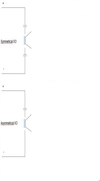
Below is my understanding of a Symmetrical Crossover, at least in the Gauder Akustik context, sorry for my poor drawing skills.

XO.jpg
 
Hmmm... I think we are at a technical gulf. That is totally different than the usual definition of symmetry as applied to filter (crossover) design. I see no advantage in an additional capacitor like that in a crossover network. If the two series capacitors are each twice the value of the one below the response will be identical. It looks like an attempt to provide some sort of balanced drive, but current flows in a loop so whether you stick a single capacitor in the (+) lead, the (-) lead, or one in each lead, the end result is the same. Except now you have twice the number of capacitors. The argument is much the same if you showed inductors instead of capacitors. So why do it?

I can think of a couple of reasons:
  1. You may be able to obtain higher order with fewer shunt (parallel) components (not shown in your diagram).
  2. If the amplifier's output is balanced, you can run balanced all the way to the speaker and provide a two-wire signal path with an additional shield around them, like an XLR connection for speakers. This could help reject noise pickup on the speaker runs, though at speaker levels noise is rarely an issue in the home, adn at the end you have a big coil of wire in the speaker to pick up anything that's out there anyway.

As far as impedances and such, assuming the same driver and crossover frequency, nothing should change as far as what the amplifier sees. My best guess, given very high order crossovers have been raised in this thread, is that (1) is the reason as it may make it simpler to obtain very high slopes. The symmetry in the filter can also be used to help reject noise that can get coupled into the inductors in a crossover.

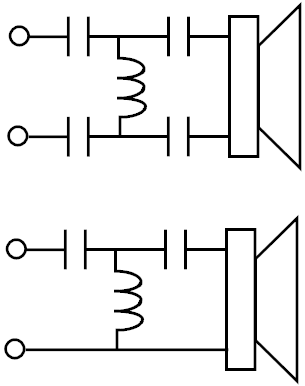
Electrically there is no difference in the two crossovers below (with appropriate choice of component values) though the circuit topology is different.

crossover.png
 
No, you can't run a shield to the speaker. It only results in phase shift (bad sound).

There's numerous balanced amplifiers that work with "asymmetric" filters. Having two caps in parallel means you have to double their size to get the original value you had with one. The amp may see more crossover distortion, too.

There may be some subjective differences, but I'm not sure of any notable electrical ones off the top of my head.
 
Electrically there is no difference in the two crossovers below (with appropriate choice of component values) though the circuit topology is different.

View attachment 26011

In one you have a high pass on both sides of the inductor, in the other you don't. The problem isn't that you may not be able to adjust for this with values to make the filter achieve the same effect, it's that by doing so the speaker may have changed the range of frequencies it can play. In this case I don't think the example works.
 
The shield is not one of the signal wires, not sure how that results in a bad-sounding speaker. It does add capacitance to both signal wires, ideally symmetric (equal to both signal wires), but that is in the mud compared to the speaker's impedance (including drivers and crossovers).

The two circuits both provide a high-pass filter to the speaker. As far as the amplifier and driver are concerned they are identical (with appropriate choices of component values).

I'm not 100% on the speaker filter.

But on the shielded cables I am. The amplifier I've spent the most time developing is balanced, and I've tried shielded cables. Other experts have chimed in on the idea too, it just doesn't work right.
 
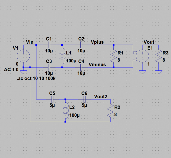
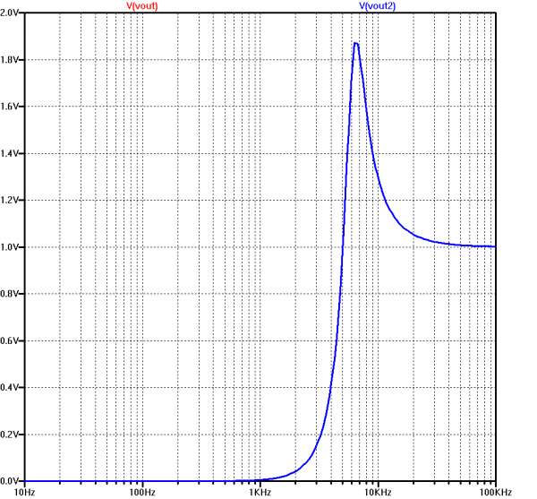
Maybe this will help -- a quick simulation showing the transfer function of the two circuits. They overlie with capacitor values in the bottom circuit equal to one-half the values in the upper circuit as expected. Vout uses a unity-gain ideal sensing source across the 8-ohm "speaker" load to make it easier to plot since the default is ground-referenced. Both have exactly the same (high-pass) transfer function.

On shielded cables, that does not make sense to me unless the amplifier is very sensitive to common-mode load capacitance, but I'll leave sonic impressions to those of you with better ears than I. In the pro world I used balanced and shielded cables all the time for long microphone and line-level runs but rarely shielded and amplifier run (sometimes had to).

crossover_sch.png

crossover_xfr.png
 
Thanks Don, I should have done the same before opening my big mouth.

Changing a crossover like that may sound better, may not. The sonic signiture will be stronger from the caps and may lead to less feedback affect on a lower level as the caps will smooth out the signal to a degree. Perhaps with ceramic drivers this is preferable, I couldn't say.

It's going to cost a lot more, at the very least.
 

About us

  • What’s Best Forum is THE forum for high end audio, product reviews, advice and sharing experiences on the best of everything else. This is THE place where audiophiles and audio companies discuss vintage, contemporary and new audio products, music servers, music streamers, computer audio, digital-to-analog converters, turntables, phono stages, cartridges, reel-to-reel tape machines, speakers, headphones and tube and solid-state amplification. Founded in 2010 What’s Best Forum invites intelligent and courteous people of all interests and backgrounds to describe and discuss the best of everything. From beginners to life-long hobbyists to industry professionals, we enjoy learning about new things and meeting new people, and participating in spirited debates.

Quick Navigation

User Menu