The big lie - Dispersion Horizontal: 30 Degrees

kach22i

WBF Founding Member
Apr 21, 2010
1,591
210
1,635
Ann Arbor, Michigan
www.kachadoorian.com
https://www.hifiplus.com/articles/m...1a-hybrid-electrostatic-loudspeaker-1/?page=3
Dispersion Horizontal: 30 Degrees

Dispersion Horizontal: 30 Degrees............what exactly does that mean?

Polar radiation pattern lobes on the M/L hybrids at let's say 400Hz to 500Hz are 3D pear or strawberry shaped, correct?

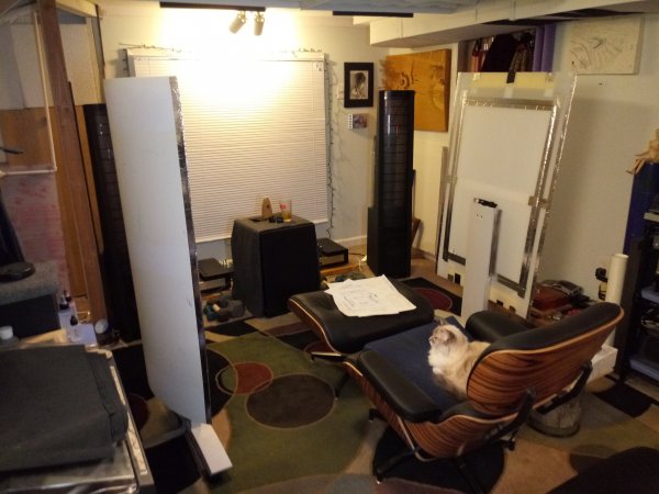
Now that I have my old Aerius speakers set up in a near idea room I find the stereo imaging sweetspot no more narrow than conventional speakers, and 1st plus 2nd reflection points using a mirror are important.

In addition, recently installed ceiling acoustic treatments have heightened the imaging scale in the vertical.

How can this happen if the wave launch or projection of sound is planar?

Is what we have been told for decades been a big lie?

That is to say, are M/L' s really narrow dispersion?
 

DonH50

Member Sponsor & WBF Technical Expert
Jun 22, 2010
3,947
306
1,670
Monument, CO
ML panels are curved to provide greater horizontal dispersion than a perfectly flat panel.

As wavelengths approach panel size they become less directional so at lower frequency any panel, curved or not, becomes more like a point source with greater dispersion (in all directions).

HTH - Don
 

kach22i

WBF Founding Member
Apr 21, 2010
1,591
210
1,635
Ann Arbor, Michigan
www.kachadoorian.com
ML panels are curved to provide greater horizontal dispersion than a perfectly flat panel.

As wavelengths approach panel size they become less directional so at lower frequency any panel, curved or not, becomes more like a point source with greater dispersion (in all directions).

HTH - Don
Took me a while to get back to this, last night's room adjustment reminded of it.

The first three feet adjacent to my right speaker now more closely matches that of the left speaker. Picture a blank front wall, the side walls that intersect at 90 degree angles, one was soft, one was hard. And I could hear the imbalance, so the first three feet of both walls are now matching and soft (offering some absorption).

Regarding frequency plot dispersion lobe (directivity) of stats, see image in post #6 below.

https://hydrogenaud.io/index.php?topic=115331.0

That image is from here:

Essence Electrostatic Model 1600
https://www.princeton.edu/3D3A/Directivity/Essence Electrostatic Model 1600/index_H.html

I have yet to find such a plot on a Martin Logan hybrid.

However in my opinion the plot linked to looks similar NOT different from that of conventional dynamic drivers. Except it's front and back dipolar of course.

In short, I think DonH50 may be correct, and my ears may be correct and the 30 degree dispersion thing is a misdirect to excuse a narrow sweetspot of other unknown or undiscussed/undisclosed cause.
 
Last edited:

Ron Resnick

Site Co-Owner, Administrator
Jan 24, 2015
16,017
13,346
2,665
Beverly Hills, CA
I am not following the OP. What is the alleged "lie"?

Don't virtually all ML owners know that their "sweet spot" is narrower than some other designs?
 

kach22i

WBF Founding Member
Apr 21, 2010
1,591
210
1,635
Ann Arbor, Michigan
www.kachadoorian.com
I am not following the OP. What is the alleged "lie"?

Don't virtually all ML owners know that their "sweet spot" is narrower than some other designs?
Not all dispersion is to the inside of the soundstage even with generous toe-in a great deal of first/early reflection is experienced.

Maybe not as bad with wide rooms or like in my old house an archway between living room and dining room.

To picture what I have resorted to, my latest DIY proof of concept diffraction device.

20200524_163500.jpg

On wheels, and yes it works wonderfully. Just hatched today.

The furry blankets are now removed, but show first reflection points.

I tried draping the furry blankets over the curved diffuser but it started to kill the liveliness.

The only absorption is a strip of carpet under pad suspended in the airspace.

The foam on the walls is old packing foam on second reflection points.

Now had the Martin Logan had true 30 degree dispersion at all frequencies my earlier diffusion and absorption devices that were set further back into the room would have been the end of my acoustic experimentation.

Show me the polar dispersion chart for M/L's.

Show me the 30 degrees.
 

Attachments

  • 20200524_163544.jpg
    20200524_163544.jpg
    480.2 KB · Views: 7
  • 20200524_153147.jpg
    20200524_153147.jpg
    540 KB · Views: 7
  • 20200524_163637.jpg
    20200524_163637.jpg
    513.9 KB · Views: 7
  • 20200524_153235.jpg
    20200524_153235.jpg
    309.2 KB · Views: 7
  • 20200524_162007.jpg
    20200524_162007.jpg
    477 KB · Views: 7
  • 20200524_153422.jpg
    20200524_153422.jpg
    422.2 KB · Views: 6
  • 20200524_161955.jpg
    20200524_161955.jpg
    526 KB · Views: 6
  • 20200524_162019.jpg
    20200524_162019.jpg
    536.4 KB · Views: 6
  • Like
Reactions: Duke LeJeune

kach22i

WBF Founding Member
Apr 21, 2010
1,591
210
1,635
Ann Arbor, Michigan
www.kachadoorian.com
Unlike most people, I have drafting triangles with 30 degree settings.

20200524_181705.jpg 20200524_181615.jpg 20200524_182638.jpg 20200524_182608.jpg

Did two different ways, second way is more accurate but still an approximation.

In short, with toe-in shown following the 1/3 rule flashlight method, 30 degrees is parallel to the side wall more or less.

Meaning there would be no first and no second reflections at all.

This is not the case in my room, I can assure you.
 
Last edited:
  • Like
Reactions: Duke LeJeune

kach22i

WBF Founding Member
Apr 21, 2010
1,591
210
1,635
Ann Arbor, Michigan
www.kachadoorian.com
I split the difference between a perpendicular to the tangent arc and just going 30 degrees off the flat corner trim as shown by the white zip-tie.

Again, if all frequencies or even just the high frequencies followed this path the diffusers I just built would not be the wonderful things they are and side wall treatments of any kind would not be needed.

20200524_184008.jpg
 

kach22i

WBF Founding Member
Apr 21, 2010
1,591
210
1,635
Ann Arbor, Michigan
www.kachadoorian.com
I'm not sure if this means anything, or if it is the key to it all.

I have my adjustable triangle set at 90 degree to tangent of panel curve/arc.

The larger 30/60 triangle is set against the adjustable triangle giving me 30 degrees off the perpendicular.

The white zip-tie laid parallel to the 30/60 points to the midpoint of the back of my diffuser which is in fact set as first early reflection point using the mirror method.

Odd, or the 30 degree dispersion claim applies from the curve, that is set off from the panel curve from an imaginary perpendicular from the tangent line. 20200524_185025.jpg
 

Duke LeJeune

[Industry Expert]/Member Sponsor
Jul 22, 2013
747
1,200
435
Princeton, Texas
My understanding of the conventional use of the term "beamwidth" is, the angle at which the SPL is down by 6 dB at either edge.

The curved panel on the Martin Logans approximates a vertical slice of an expanding cylinder, such that it radiates highs uniformly across its arc, rather then beaming them severely like a flat panel of the same width would.

So if the actual physical curvature of the Martin Logan's panel is a 20 degree arc, and its output falls off at the edges such that it's -6 dB another 5 degrees to either side, the effective "beamwidth" would be 20 + 5 + 5 = 30 degrees. In other words, you'd have good high frequency coverage out to 15 degrees on either side of the centerline.

This would hold true for wavelengths shorter than the panel's width, which includes the frequencies we get most of our image localization from. So while "30 degrees" doesn't hold true across the spectrum, it's probably a good representation of the effective radiation pattern width.

At wavelengths which are long relative to the panel's width the radiation pattern widens, and starts to look like the "squashed figure-8" of a textbook dipole.

The radiation pattern of the point-source-approximating woofer will generally be wider than that of the line-source-approximating panel, especially in the vertical plane. Sound pressure level falls off more slowly with distance from a line source than from a point source, so the SPL will generally fall off more slowly with distance from the panel than from the woofer. This discrepancy presents one of the challenges of designing and using a hybrid electrostatic speaker: The tonal balance can change with distance.
 
  • Like
Reactions: kach22i

About us

  • What’s Best Forum is THE forum for high end audio, product reviews, advice and sharing experiences on the best of everything else. This is THE place where audiophiles and audio companies discuss vintage, contemporary and new audio products, music servers, music streamers, computer audio, digital-to-analog converters, turntables, phono stages, cartridges, reel-to-reel tape machines, speakers, headphones and tube and solid-state amplification. Founded in 2010 What’s Best Forum invites intelligent and courteous people of all interests and backgrounds to describe and discuss the best of everything. From beginners to life-long hobbyists to industry professionals, we enjoy learning about new things and meeting new people, and participating in spirited debates.

Quick Navigation

User Menu

Steve Williams
Site Founder | Site Owner | Administrator
Ron Resnick
Site Co-Owner | Administrator
Julian (The Fixer)
Website Build | Marketing Managersing