"What The Specs Don’t Tell You… And Why"

@AP, I've been talking about using multitone test signals as more appropriate & know AP scopes have some capabilities in this area - care to talk about that?
One thing I was interested in is using these multitone test signals to test for noise floor modulation - any ideas how this might be done?
Multitones are steady state signals so I wouldn't expect them to highlight noise floor modulation. However, I have not done any testing to look for noise floor modulation. One could change the relative phase of the tones and thus change the crest factor of a multitone without changing its harmonic content. I wouldn't expect the noise level to change with crest factor but if it does, it would be worth investigating why.

The AP multitone analysis uses a synchronous set of tones. This allows us to use a windowless FFT in order to get accurate results across a very wide bandwidth. We can extract frequency response, noise, phase, crosstalk and total distortion with one acquisition. The total distortion number is a summation of the harmonics of all the tones and the IM products of each tone mixed with the other. The more tones you have, the higher the TD will be. This makes correlating TD to standard THD and IMD measurements difficult.

ESS has given papers in the past about noise floor modulation in DACs. If I recall correctly, they measured this by simply changing DC levels between two states and recording the noise w.r.t. time. I couldn't find the paper and it was many years ago. My memory could be failing me.
 
Multitones are steady state signals so I wouldn't expect them to highlight noise floor modulation.

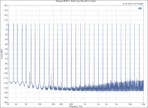
What do you mean by 'steady state' here? They're not 'stationary' signals in the way that, for example, a single sinewave is - in that they occupy finite bandwidth. If you go over here where a poster on DIYA has tested his composite amp with a 32 tone signal, there is some 'fill-in' between the tones at higher freqs which to me is indicative of noise floor modulation. http://www.neurochrome.com/modulus-86-rev-2-1/ - scroll down to the last-but-one FFT.

The AP multitone analysis uses a synchronous set of tones. This allows us to use a windowless FFT in order to get accurate results across a very wide bandwidth. We can extract frequency response, noise, phase, crosstalk and total distortion with one acquisition. The total distortion number is a summation of the harmonics of all the tones and the IM products of each tone mixed with the other. The more tones you have, the higher the TD will be. This makes correlating TD to standard THD and IMD measurements difficult.

I've had discussions with designers on DIYA and its common to see your last point denied - i.e. that multitone brings nothing new to the table over and above standard THD and IMD measurements. Refreshing to see acceptance of this fact.

ESS has given papers in the past about noise floor modulation in DACs. If I recall correctly, they measured this by simply changing DC levels between two states and recording the noise w.r.t. time. I couldn't find the paper and it was many years ago. My memory could be failing me.

They showed plots I think within the RMAF presentation you can (once again) find on Youtube, but as I recall those plots were quite misleading. Likewise, my memory might be failing me.
 
What do you mean by 'steady state' here? They're not 'stationary' signals in the way that, for example, a single sinewave is - in that they occupy finite bandwidth.
The multi-tone used in the DIYA post consists of 32 steady state sine waves. It is a synchronous signal which means it repeats without discontinuity. That is what I meant by steady state.

If you go over here where a poster on DIYA has tested his composite amp with a 32 tone signal, there is some 'fill-in' between the tones at higher freqs which to me is indicative of noise floor modulation. http://www.neurochrome.com/modulus-86-rev-2-1/ - scroll down to the last-but-one FFT.
Perhaps we have a semantic difference here. When I think of noise in a multitone, I am not thinking of the harmonics and intermods. The spectrum will shows the IMD and THD products which can mask the true noise floor. The true noise floor is shown on a different graph labelled noise spectral density. To produce the noise spectral density, we only look at the FFT bins that do not contain fundamental tones, harmonics or intermods. Then we normalize the level of the noise bins according to the FFT bin width hence the result is volts per root-hertz.

I've had discussions with designers on DIYA and its common to see your last point denied - i.e. that multitone brings nothing new to the table over and above standard THD and IMD measurements. Refreshing to see acceptance of this fact.
Multitones do have many advantages in a variety of circumstances. For instance, feedback cancellation algorithms within speech processors (think hands-free BT devices) may kill a pure sine tone and thus make certain tests impossible. Multitones can get past such algorithms. They are also great for taxing lossy codecs whereas a single sine wave will pass through with ease. Multitones are also faster than stepped sweeps. The downside is that to correlate a TD number to a traditional THD or IMD number, you really need to study known good and known bad devices to set a threshold limit.

They showed plots I think within the RMAF presentation you can (once again) find on Youtube, but as I recall those plots were quite misleading. Likewise, my memory might be failing me.
Now that you mention it, I may have seen the RMAF presentation.
 
Thanks for the reply AP & OPus & Don's posts too.
I believe what Opus is saying is that in the 32 tone test graph seen here - the IM & harmonics are seen as a "grass of harmonics" between the tones (except at LF where they are close-in harmonics, causing the base spreading of the tone). From this it may be extrapolated that with music (> 32 multi tones) we will see a more dense "grass" (i.e it effectively becomes a noise floor, perceptually) & as the music (tones) fluctuates so too will this "IM grass"/noise floor.

Q: Would you expect the IM products see in this graph to change with the crest factor of the 32 tones?

Modulus-86-R2.1_-Multi-Tone-Test-40-W-8-ohm-687x500.png

The ESS video is again on youtube & the part where he discusses noise floor modulation is here:
[video]https://youtu.be/8Mn5PrnZV-k?t=2072[/video]
 
Last edited:
IMD is vexing for a couple of reasons. It is higher in amplitude than the same order THD for equivalent signal levels (e.g. third-order IMD is 9.54 dB higher than third-order HD) and produces non-harmonic spurs that sound worse than harmonic spurs.

I didn't look at the video (no access currently) but noise floor modulation I have seen defined several ways and attributed to several causes. There is the fundamental noise shaping in a delta-sigma converter (ADC or DAC), amplitude modulation with the signal (which may relate to the digital filters used in a delta-sigma design or basic circuit theory in analog cells operating in their high-gain region), modulation due to nonlinear (distortion) products (IMD/THD/etc.), aperture and other jitter, etc.

Apologies if not relevant, I have not read this whole thread, just checking in and caught my eye. - Don
 
IMD is vexing for a couple of reasons. It is higher in amplitude than the same order THD for equivalent signal levels (e.g. third-order IMD is 9.54 dB higher than third-order HD) and produces non-harmonic spurs that sound worse than harmonic spurs.
Yes, so psychoacoustically of more importance than harmonic spurs

I didn't look at the video (no access currently) but noise floor modulation I have seen defined several ways and attributed to several causes. There is the fundamental noise shaping in a delta-sigma converter (ADC or DAC), amplitude modulation with the signal (which may relate to the digital filters used in a delta-sigma design or basic circuit theory in analog cells operating in their high-gain region), modulation due to nonlinear (distortion) products (IMD/THD/etc.), aperture and other jitter, etc.

Apologies if not relevant, I have not read this whole thread, just checking in and caught my eye. - Don
[/quote]What Mallinson states (I paraphrase) in that video is that "what audiophiles are hearing (that is anomalous) is non periodic steady state noise" "You will not find Non-PSS noise by looking at THD, DNR & SNR - in a periodic steady state you do not activate this form of noise but it is revealed by a plot of noise Vs DC offset"

It's an interesting area that appears is missed by most standard audio testing?
 
jkeny, thanks for finding that video. That was the presentation I was referring to in my earlier post. You will notice that the noise described is being measured using an AP analyzer that many people own. However, few people take the time to conduct this kind of test. This is frustrating to me and part of my motivation for putting that talk together. Most designers have the tools to get more meaningful results but they don't make the effort to use them. I suspect part of this problem that they don't appreciate how insufficient the commonly published specs are. The other major problem is having the time to do anything more than is minimally required.

Here is an interesting article written by AP's co-founder Bruce Hofer http://www.ap.com/display/file/747 and its corresponding slides http://www.ap.com/display/file/592. What is interesting about this is the amount of component level analysis that goes into low noise and low THD products like our analyzers. It isn't rocket science. It is just a matter of paying attention to the small details. One of those details is the nonlinear voltage coefficients on resistor and capacitor distortions. This would lead to me to believe that one might be able to see finite differences in residual noise and distortion based on changes in the crest factor of similar multitones.
 
@jkeny -- thanks for that!

Random noise can come from many sources but I suspect my definitions and background differ. Noise in delta-sigma converters related to DC offset can come from limit cycles in the digital filters, something dither and fancy design can help alleviate, and NTF (noise transfer function) changes in the modulator's circuits as the input DC (common-mode) level changes, changing the gain and noise sensitivity of various internal circuits.

An example of noise floor modulation that can be rather annoying is the "pumping" that can occur when excessive compression and/or limiters are used during recording (or playback). Back when I had a full dbx setup I found that highly annoying with certain source material, like single notes or drumbeats spaced apart so the noise floor rose with each beat.

Other sources of random, or deterministic noise unrelated to the signal, include clock and data crosstalk, power supply noise, EMI/RFI, etc.

@AP Jonathan -- So the devil's in the details? :) So true... Most resistors are pretty durn linear, but on-chip resistors suffer from all sorts of gnarly little effects, including nonlinear voltage coefficients, all sorts of noise (not just thermal), and so forth. Capacitors discrete or integrated can suffer from nonlinear voltage variation, noise, hysteresis, and all that jazz. Layout of the boards and wires is also extremely critical when attacking such low noise and crosstalk floors.

My worst nightmares back in my tech days were not the blown-up amplifiers, it was the ones that exhibited 0.01% THD instead of 0.001%. Inaudible, but often a real pain to debug and fix.
 
The other thing that Mallinson mentions in his video is something he calls "nonlinear excess phase" of sigma delta modulators & that this is a variable delay related to signal & "every sigma delta modulator will eventually oscillate at some high signal level". "Unconditional stability or modulators that don't oscillate" he also states is audible because these various characteristics can be simulated in FPGA turned on/off

I don't believe he mentions any measurement but I'm sure this oscillation should be easy to measure? I wonder if anyone has an example of such measurements?

The other thing of great interest is just how far down these audible effects are - the noise floor modulation @ -100dB
 
Last edited:
The other thing that Mallinson mentions in his video is something he calls "nonlinear excess phase" of sigma delta modulators & that this is a variable delay related to signal & "every sigma delta modulator will eventually oscillate at some high signal level". "Unconditional stability or modulators that don't oscillate" he also states is audible because these various characteristics can be simulated in FPGA turned on/off

I don't believe he mentions any measurement but I'm sure this oscillation should be easy to measure? I wonder if anyone has an example of such measurements?

The other thing of great interest is just how far down these audible effects are - the noise floor modulation @ -100dB

I tend to shy away from questions of audibility. Elsewhere an assertion was made that artifacts -140 dB down audibility corrupt the sound heard; I cannot say my ears are anywhere near that good (nor is most test equipment).

Stability of delta-sigma loops is pretty complicated. I have run into various issues designing them but do not claim to be an expert, especially for audio converters that tend to be much more complex than the RF types I have usually designed (or helped design). Two popular introductory references are by John Candy & Gabor Temes (a collection of tutorials and IEEE papers) and the more recent book by Steven Norsworthy et. al. (see below). They are both pretty old now and there are a ton of other books, natch.

The oscillation will show up in spectral analysis but there are several types of oscillatory mechanisms. Some are signal-dependent, some relate to the DC level, and some are related to basic loop stability. So, you have to know what you are looking for, and they are not always immediately obvious.

Most delta-sigma loops are digital or sampled-analog (I have also designed continuous-time (CT) modulators and they add more worms to the can). Sampling is a non-linear phenomenon and so the phase shift is nonlinear and related to the architecture (including modulator/demodulator loop design) and sampling rate. Since a delta-sigma modulator is a feedback system they can get very complicated in design and analysis. Multiple bits, multiple loops, cascading loops, etc. Stability can be a nightmare, and simulations to ensure unconditionally stability of a nonlinear sampled system are not fun. And likely to miss that one magic combination that the real world finds immediately after power-up of the fabricated device...

That said, a lot of those issues have been addressed over the years, and I would not have expected them to be significant concerns, at least not stability, these days. But then I have expected a lot of things that haven't really worked out for me... ;)

HTH - Don

Oversampling Delta-Sigma Data Converters: Theory, Design, and Simulation
James C. Candy (Editor), Gabor C. Temes (Editor)
Publisher: Wiley-IEEE Press; 1 edition (September 2, 1991)
Language: English
ISBN-10: 0879422858
ISBN-13: 978-0879422851

Delta-Sigma Data Converters: Theory, Design, and Simulation
Steven R. Norsworthy (Editor), Richard Schreier (Editor), Gabor C. Temes (Editor)
Publisher: Wiley-IEEE Press; 1 edition (October 28, 1996)
Language: English
ISBN-10: 0780310454
ISBN-13: 978-0780310452
 
I tend to shy away from questions of audibility. Elsewhere an assertion was made that artifacts -140 dB down audibility corrupt the sound heard; I cannot say my ears are anywhere near that good (nor is most test equipment).
Well the audibility question is the one that most interests me - measurements which hardly relate to audibility are of little interest. However, I'm also interested in whether the noise floor fluctuations @ -100dB is an indicator of an issue somewhere else which is audible or whether it itself is the causal audibility factor. I believe an issue in the field of psychoacoustics which is possibly relevant to the noise floor modulation relates to how various types of modulation affects our perception. There are 3 basic affects termed Comodulation Masking Release (CMR), Modulation Detection Interference (MDI) & Comodulation Difference Detection (CDD). The effect of CMR is that the threshold audibility of a signal is lowered when another signal at a remote frequency is coherently modulating. In other words we can hear a signal buried in noise better if there is another signal modulating at the same phase but spectrally remote from the signal frequency. MDI is where a spectrally remote non-coherent modulating tone (or noise) can detrimentally affect the perception of modulation of a probe tone. CDD is somewhere between these two
Natural sounds often exhibit correlated amplitude modulations at different frequency regions, so-called comodulation. Therefore, the ear might be especially adapted to these kinds of sounds.

You'll find an interesting demonstration of CMR here

Stability of delta-sigma loops is pretty complicated. I have run into various issues designing them but do not claim to be an expert, especially for audio converters that tend to be much more complex than the RF types I have usually designed (or helped design). Two popular introductory references are by John Candy & Gabor Temes (a collection of tutorials and IEEE papers) and the more recent book by Steven Norsworthy et. al. (see below). They are both pretty old now and there are a ton of other books, natch.

The oscillation will show up in spectral analysis but there are several types of oscillatory mechanisms. Some are signal-dependent, some relate to the DC level, and some are related to basic loop stability. So, you have to know what you are looking for, and they are not always immediately obvious.

Most delta-sigma loops are digital or sampled-analog (I have also designed continuous-time (CT) modulators and they add more worms to the can). Sampling is a non-linear phenomenon and so the phase shift is nonlinear and related to the architecture (including modulator/demodulator loop design) and sampling rate. Since a delta-sigma modulator is a feedback system they can get very complicated in design and analysis. Multiple bits, multiple loops, cascading loops, etc. Stability can be a nightmare, and simulations to ensure unconditionally stability of a nonlinear sampled system are not fun. And likely to miss that one magic combination that the real world finds immediately after power-up of the fabricated device...

That said, a lot of those issues have been addressed over the years, and I would not have expected them to be significant concerns, at least not stability, these days. But then I have expected a lot of things that haven't really worked out for me... ;)

HTH - Don

Oversampling Delta-Sigma Data Converters: Theory, Design, and Simulation
James C. Candy (Editor), Gabor C. Temes (Editor)
Publisher: Wiley-IEEE Press; 1 edition (September 2, 1991)
Language: English
ISBN-10: 0879422858
ISBN-13: 978-0879422851

Delta-Sigma Data Converters: Theory, Design, and Simulation
Steven R. Norsworthy (Editor), Richard Schreier (Editor), Gabor C. Temes (Editor)
Publisher: Wiley-IEEE Press; 1 edition (October 28, 1996)
Language: English
ISBN-10: 0780310454
ISBN-13: 978-0780310452
Thanks, Don, much appreciate your input & experience in delta sigma design issues.
 
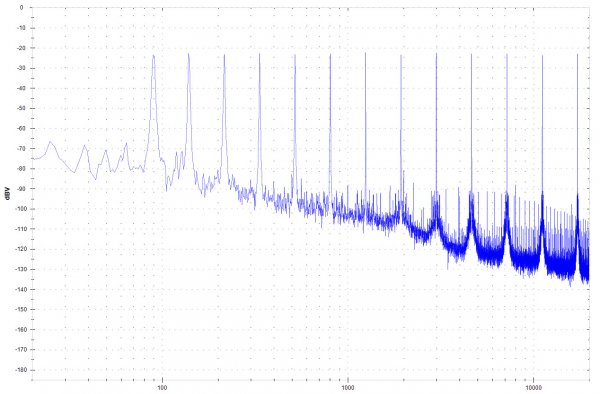
I came across similar multitone measurements being used by this guy

sample-spectrum.jpg

Quoted text from the webpage:
"As you might have noticed, the output of the device has extra tones that look like grass in between the original tones. They are the result of distortions in the signal. Now we measure the energy of these extra tones + noise. This give us one number that is the total distortion + noise, or TD+N. Comparing two DACs this way will tell you which one sounds clearer. It’s simple.
Higher is bad. Lower is good. It’s like golf!
This measurement doesn't tell you everything there is to know about a DAC. But, it measures what I consider to be the most important factor in determining sound quality for a DAC, its clarity. So I call it the Sound Clarity Score.
It also can be used to measure more than just DACs. So, we are going to measure the Clarity Score for everything that we can think of, and publish the results on this blog. Hopefully, we will elevate our knowledge of computer audio, bust some myths, make some people angry, and in the process bring some clarity to the world of computer audio .​

He also credits the origin of the concept:
"I also should mention I didn’t come up with this measurement in vacuum. This test was inspired by the work of Deane Jensen (who was trying to achieve the same goal for vacuum tube amplifiers) and others. You can find Deane's paper here.​
 
IN following up Jensen's paper "Spectral Contamination Measurement" I came across Jon Risch's pdf where he uses a different set of multitones chosen so that the IMD products don't overlap "What I wanted was a spacing ratio that would make as many of the products spaced away from one another and from the original tones as much as possible. Eventually, I found that the ratio known as Phi, or the Golden Ratio, did the trick."

The PDF also includes his AES paper "A NEW CLASS OF IN-BAND MULTITONE TEST SIGNALS" explains the technique further

The full paper is here
 
Last edited:
TD+N is a new one on me -- I think that is SINAD (signal to noise and distortion) to most of us. I have seen THD+N but that is not the same as SINAD (or TD+N if you prefer). Most audio analyzers use THD+N and that generally provides a rising curve at low power as the noise rises relative to the signal so is somewhat misleading IMO.

I skimmed the paper and it looks interesting. The IEEE ADC Standard (1241, IIRC -- my boss was on the committee and I helped review it) discusses the methodology for generating test tones that bin perfectly and are non-overlapping. It relies on relatively prime numbers. That also obviates FFT windowing, making testing much simpler and more exact. I use that method in all my various Mathcad and Matlab programs used to generate the various plots in my little articles here as well as for real work (single and multitone).
 
TD+N is a new one on me -- I think that is SINAD (signal to noise and distortion) to most of us.
SINAD is strictly the inverse of THD+N; just swap the numerator and denominator. SINAD is measured with a single tone just as with THD+N. TD+N is based on multitones and includes the harmonics of all the fundamentals and the IM products of each tone interacting with the others. If you limit the number of tones, it is not too difficult to keep the IM products away from harmonics. This can let you look at specific bins of the FFT and calculate THD+N and twin tone IMD products.
 
Not in my world, but my world is not usually audio measurements. SINAD includes harmonic and non-harmonic spurs; THD+N includes total harmonic distortion plus noise, no other correlated spurs. It is true a lot of test equipment treats SINAD and THD+N the same, which was sort of my earlier point. And we do multi-frequency SINAD, and sometimes the signal is pretty complex when it is serial data or a communications or telemetry signal.

But, now I see the distinction between TD+N and THD+N, thank you! Obvious in hindsight... To me, SINAD and TD+N would be the same, but we're down to semantics, I think. SINAD leads to the ENOB (effective number of bits) for a data converter (ADC or DAC); THD+N does not (again, using the definitions I have used for ages and have always had to report).

The IEEE Standard is what I use to bin signals in the FFTs without overlap, or sometimes the old relatively prime method (which works out to pretty much the same thing).

No worries - Don
 

About us

  • What’s Best Forum is THE forum for high end audio, product reviews, advice and sharing experiences on the best of everything else. This is THE place where audiophiles and audio companies discuss vintage, contemporary and new audio products, music servers, music streamers, computer audio, digital-to-analog converters, turntables, phono stages, cartridges, reel-to-reel tape machines, speakers, headphones and tube and solid-state amplification. Founded in 2010 What’s Best Forum invites intelligent and courteous people of all interests and backgrounds to describe and discuss the best of everything. From beginners to life-long hobbyists to industry professionals, we enjoy learning about new things and meeting new people, and participating in spirited debates.

Quick Navigation

User Menu