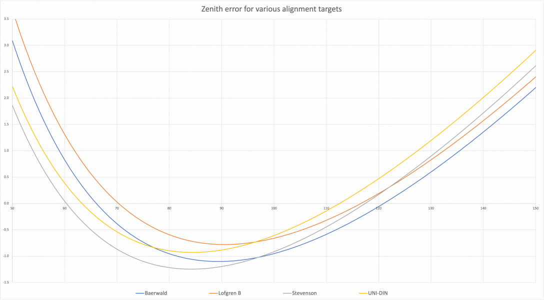
Baerwald? LofgrenB? Stevenson? The math behind alignment conventions

No, they are not chosen arbitrarily when it comes to Lofgren A, B, Stevenson or UNI-DIN. Those null points are chosen in order to reach design goals of each geometry over the recorded area of vinyl record. The limits of the recorded area is determined by the standard (IEC, DIN, JIS) which inevitably changes null points.

Everybody agrees on this but you don't. It is unbelievable to see you still arguing. Please do some research.
Like I said previously, the “design goal” is where I want the least distortion - which would be exactly zero at the null points but non-zero elsewhere. There’s absolutely nothing magical here. If I change the null point slightly I will get a slightly different zenith error at a given radius. ALL of this is in accordance to the formulas posted above.

Just try the exercise I suggested and you will see. I just did for the kicks of it. I took the table you posted above, and calculated the two null points according to the formula:

IMG_3989.jpeg

and compared it to the null points in the table. Within 0.0x mm they tie out in every case.

Please make sure that the appropriate angle conversions are used or your results will be wrong. For example my Excel’s “cos” assumes angles in radians, so the argument for the null points calc should be (90-tau)*Pi/180, not 90-tau.
 
Last edited:
  • Like
Reactions: Another Johnson
Like I said previously, the “design goal” is where I want the least distortion - which would be exactly zero at the null points but non-zero elsewhere. There’s absolutely nothing magical here. If I change the null point slightly I will get a slightly different zenith error at a given radius. ALL of this is in accordance to the formulas posted above.

Just try the exercise I suggested and you will see. I just did for the kicks of it. Within 0.0x mm they tie out in every case. Please make sure that the appropriate angle conversions are used or your results will be wrong. For example my Excel’s “cos” assumes angles in radians, so the argument for the null points calc should be (90-tau)*Pi/180, not 90-tau.
The problem with your approach that you think null points are pre determined and you based all the formulation around it. Null points are not pre determined. Null points are the product of each geometry's design approach. There are 3 things given beforehand these calculations.
- Pivot to spindle distance or effective length
- Working area (Inner and outer radiuses)
- Desired distortion curve inside that working area. (Ex. Same distortion figures at 3 peak points or lowest distortion at innermost groove etc)

The goal is to determine overhang and offset angle. Null points are just the result of this.
I don’t disagree that a design goal could be either a max distortion between inner and outer grooves or a max average, that’s fine.

The formulas above simply calculate zenith error from just three geometry components: ra, rps, and tau. And the key point is those are the only parameters that matter
 
Last edited:
  • Like
Reactions: Another Johnson
I don

I don’t disagree that a design goal could be either a max distortion between inner and outer grooves or a max average, that’s fine.

The formulas above simply calculate zenith error from just three geometry components: ra, rps, and tau. And the key point is those are the only parameters that matter
Where do you get that offset angle and overhang to use in your formula? Or even better let me put it this way, where do you get those null points? Why do you easily accept fixed null points that you find online without questioning while questioning all the information and writing your own formula? Did you ever stop and think about that?
 
Where do you get that offset angle and overhang to use in your formula? Or even better let me put it this way, where do you get those null points? Why do you easily accept fixed null points that you find online without questioning while questioning all the information and writing your own formula? Did you ever stop and think about that?
QUITE simple:

Say you drilled the hole for you arm, so rps is fixed. Say my design goal is err1 for whatever I consider the inner radius and err2 for whatever I consider the outer radius. My formula will let you determine tau (offset angle) and overhang. Or equivalently the two null points (you have two degrees of freedom to determine). This is just an example.
 
  • Like
Reactions: Another Johnson
Say you drilled the hole for you arm, so rps is fixed. Say my design goal is err1 for whatever I consider the inner radius and err2 for whatever I consider the outer radius. My formula will let you determine tau (offset angle) and overhang. Or equivalently the two null points (you have two degrees of freedom to determine). This is just an example.
I already told you all about it with this:
Null points are the product of each geometry's design approach. There are 3 things given beforehand these calculations.
- Pivot to spindle distance or effective length
- Working area (Inner and outer radiuses)
- Desired distortion curve inside that working area. (Ex. Same distortion figures at 3 peak points or lowest distortion at innermost groove etc)

The goal is to determine overhang and offset angle. Null points are just the result of this.


After all that long argument you say;
My formula will let you determine tau (offset angle) and overhang. Or equivalently the two null points
But before that you were saying;
The calcs are pure geometry, the null points don’t change -
That is simply unbelivable.

The formulas above simply calculate zenith error from just three geometry components: ra, rps, and tau. And the key point is those are the only parameters that matter
You mean P2S distance, overhang and offset angle in your words. No the key point is not those parameters because you don't know the overhang and offset angle beforehand. The key point is doing calculations for a given P2S distance (or effective length) and inner and outer radiuses. Calculations give you overhang, offset angle and null points.

I keep repeating myself and said more than enough. Just check the graphs and tables I shared and check yours.
 
Last edited:
This seems to be a debate between a thinker and a reader.

Note that none of the pivoting tonearms can achieve error free set up over the whole arc of tonearm motion. But errors are always small.

People like their TT/tonearm setups, many arguing that vinyl gives superior sound.

How many angels can dance on the tip of a stylus? No one knows. But we do know that these detailed arguments don’t make the music sound uniformly better.

Cartridge set up is more about arguing than about music. Pick the setup you like, and enjoy your records.

FWIW, I like the OP’s initiative and presentation.
 
Last edited:
  • Like
Reactions: miglto
(...) Note that none of the pivoting tonearms can achieve error free set up over the whole arc of tonearm motion.

Yes, different alignments are simply different compromises involving complex situations such as the linear speed of the vinyl LP and the statistical distribution of the recording areas. It was a regular subject in Wireless World and audio magazines in the 60's and 70's.

But errors are always small. (...)

We say so it until we get used to a good parallel tracking tonearm ... ;)
 
  • Like
Reactions: marty
Cartridge set up is more about arguing than about music. Pick the setup you like, and enjoy your records.
Indeed music is the most important thing we are after.

However, proper turntable setup will make a big difference in sound quality, which is why we bother with this. Arguably some of the nitty gritty of arguing about Baerwald vs Lofgren is not all that critical.

The calculation I started off this thread with is just meant for my understanding of what matters and answering questions like:
- What constraints limit the position of the null points if any?
- How much do I need to change the offset angle and overhang to go from one convention to the next?
- What is the functional form of the zenith error so I can understand what is my preferred location for null points?

I also think that some inquisitive minds out there might find it interesting or useful to have the exact functional form of the zenith error.

Having said all this, I actually use AnalogMagik (v2) to adjust all these parameters once I have the basic geometrical setup right. The reason is simple: most cartridges with a fine line stylus will have the fine line slightly off from the geometrical alignment of the cantilever and body. So the only way to nail this down is to optimize for the thing we want to optimize in the first place: minimal IMD. The AMv2 track for zenith, azimuth, and VTA optimization runs between 114mm and 129mm radii, so the Baerwald null is smack in the middle of the track, and the LofgrenB null is towards the end of the track.

I have found the use of a tool like AM makes a large difference in the resulting sound quality.
 
Last edited:
Indeed music is the most important thing we are after.

However, proper turntable setup will make a big difference in sound quality, which is why we bother with this. Arguably some of the nitty gritty of arguing about Baerwald vs Lofgren is not all that critical.

The calculation I started off this thread with is just meant for my understanding of what matters and answering questions like:
- What constraints limit the position of the null points if any?
- How much do I need to change the offset angle and overhang to go from one convention to the next?
- What is the functional form of the zenith error so I can understand what is my preferred location for null points?

I also think that some inquisitive minds out there might find it interesting or useful to have the exact functional form of the zenith error.

Having said all this, I actually use AnalogMagik (v2) to adjust all these parameters once I have the basic geometrical setup right. The reason is simple: most cartridges with a fine line stylus will have the fine line slightly off from the geometrical alignment of the cantilever and body. So the only way to nail this down is to optimize for the thing we want to optimize in the first place: minimal IMD. The AMv2 track for zenith, azimuth, and VTA optimization runs between 114mm and 129mm radii, so the Baerwald null is smack in the middle of the track, and the LofgrenB null is towards the end of the track.

I have found the use of a tool like AM makes a large difference in the resulting sound quality.
Here's another interesting point about having done the math: It shows that the zenith error function shape depends only on ra and rps. The value of tau is a constant that shifts this shape up and down.

Now say I did all the geometrical setup for Baerwald. Now I use AnalogMagik to fine tune the cartridge zenith angle to get the minimum IMD (InterModulation Distortion). If I aim for the middle of the test track to show minimal IMD then I will be calibrating strictly to Baerwald since that's where the null point is initially in my geometric setup, and that's perfectly fine. What this calibration does is it corrects for any internal misalignment of the contact edges of the stylus and the cantilever - when doing the geometrical setup all you can use is the cantilever, but you would really want is to be able to see the contact edges, which of course is impossible.

However, if instead I aim for the minimum IMD at the end of the test track, I would be setting a tau that puts the effective outer null point there, and because I know this just produces a vertical shift of the zenith error function, the inner null point comes in a little closer to the outer one, effectively rendering something close to a LofgrenB alignment.

The names and conventions here are not important, what matters is in the first case I would be adjusting zenith so that I have lower distortion at the beginning and end by sacrificing more error in the middle whereas in the second case I would be adjusting it so that it is a little lower in the middle, at the expense of a little more distortion at beginning and end.

Zenith Error.png
 
Last edited:
Indeed music is the most important thing we are after.

However, proper turntable setup will make a big difference in sound quality, which is why we bother with this. Arguably some of the nitty gritty of arguing about Baerwald vs Lofgren is not all that critical.

Yes, proper set up is important. But which to use? It depends on the specific record’s flaws. And none of these are doing what we think they’re doing if the center hole is punched with eccentricity. You could add eccentricity to your model, or you could do the analysis stochastically.

But it wouldn’t make your records sound better.

Chasing (and adjusting for) the best set up for every recording is a fool’s errand.

Just like chasing SRA with a VTA adjustable pillar but a sloppy screw (all the VTA adjustable arms I’ve handled have had noticeable lash).

Set it up, and enjoy your records until the stylus needs an inspection. Or until you notice it is no longer pleasing.

And, as noted, I like your analysis. You would be a good mathematical design guy. My own PhD was based in mathematical programming in the early days of nonlinear programming. Not that it matters.
 
Yes, proper set up is important. But which to use? It depends on the specific record’s flaws. And none of these are doing what we think they’re doing if the center hole is punched with eccentricity. You could add eccentricity to your model, or you could do the analysis stochastically.
Indeed, but clearly getting zenith as good as possible is improving the sound. You will have other problems like wow&flutter from a non-centered whole etc, for sure. It's a matter of improving what we can to get as close as possible to the best sound we can get with the setup.

Chasing (and adjusting for) the best set up for every recording is a fool’s errand.
Agreed. I would not bother with that.

Just like chasing SRA with a VTA adjustable pillar but a sloppy screw (all the VTA adjustable arms I’ve handled have had noticeable lash).

Set it up, and enjoy your records until the stylus needs an inspection. Or until you notice it is no longer pleasing.
I am simply advocating the best possible "average" setup.
 
Found this paper (the very first formula is the same as what I got):

https://www.aes.org/tmpFiles/elib/20230925/21560.pdf

On page 201 of the AES paper you shared:

"Another useful result for Lofgren A alignment was derived in 1941 by Baerwald [7], who showed that the HTE zeros will be located at radii R01 and R02 given by


Ekran Resmi 2023-09-25 18.23.37.jpg


which depend on the disk first ( R1 ) and last ( R2 ) groove radii but are independent of the tonearm length."

"In [5], pp. S2-4–S2-5, the original Lofgren’s formulae were parametric, but presented here are the versions that show explicitly that the optimum tonearm parameters depend only on the inner (R1) and outer (R2) disk radii and tonearm length (L)."


Which means the place of null points (R01 and R02) depend on inner and outer groove radiuses (R1 and R2). When R1 and R2 changes null points change too. Which is what I’m saying from the beginning of this discussion.

On page 204:

"For the first and last groove radii R1 = 60.325 mm and R2= 146.05 mm, as standardized by the International Electrotechnical Commission"

Which means International Electrotechnical Commission (IEC) standard is used for calculations. When standard changes from IEC to DIN or JIS inner and outer groove radiuses (R1 and R2) change and as a result null points change too. It confirms what I said before.

Please read the paper you shared together with my prior comments and think about your prior comments like the ones below. BTW the UNI-DIN geometry solely depends on DIN but you keep drawing it using IEC.
The calcs are pure geometry, the null points don’t change - please see the derivations, there is no assumption at all other than geometry.
I don’t think this is right. The null points are:

IMG_3989.jpeg


And this is literally just geometry that does not depend at all on inner or outter radii.
 
Last edited:
On page 201 of the AES paper you shared:

"Another useful result for Lofgren A alignment was derived in 1941 by Baerwald [7], who showed that the HTE zeros will be located at radii R01 and R02 given by


View attachment 117159


which depend on the disk first ( R1 ) and last ( R2 ) groove radii but are independent of the tonearm length."

"In [5], pp. S2-4–S2-5, the original Lofgren’s formulae were parametric, but presented here are the versions that show explicitly that the optimum tonearm parameters depend only on the inner (R1) and outer (R2) disk radii and tonearm length (L)."


Which means the place of null points (R01 and R02) depend on inner and outer groove radiuses (R1 and R2). When R1 and R2 changes null points change too. Which is what I’m saying from the beginning of this discussion.

On page 204:

"For the first and last groove radii R1 = 60.325 mm and R2= 146.05 mm, as standardized by the International Electrotechnical Commission"

Which means International Electrotechnical Commission (IEC) standard is used for calculations. When standard changes from IEC to DIN or JIS inner and outer groove radiuses (R1 and R2) change and as a result null points change too. It confirms what I said before.

Please read the paper you shared together with my prior comments and think about your prior comments like the ones below. BTW the UNI-DIN geometry solely depends on DIN but you keep drawing it using IEC.
I have read the paper and done the equations. The very first formula in this paper is exactly the one I posted initially in this thread. Nothing here is in any contradiction to what I stated.

The point here is: given null points and effective length you can determine everything else. And that is exactly what I have said all along. The question is what null points to choose:

Lofgren A condition: Make weighted tracking error (wte = zenith angle error / r) be the same at three points: outer radius, inner radius, and the peak in the function (which is somewhere in between these two). That gives you the null points.

Lofgren B condition: Minimize wte’s RMS.

That is it. All of the equations for zenith error that I posted initially are the same here - and they don’t change with any alignment convention (ie they are geometry). What changes is where the null points are, and that’s fine. I could come up with a different set of null points and the formulas to get offset angle, etc will be exactly the same.
I understood, instead of admitting the truth you choose to keep dancing around. very well.
 
Last edited:
To reiterate as succinctly as possible:

The formula for zenith error requires only three quantities: effective length, overhang, and offset angle.

First way to use this formula: Given these three geometrical parameters, it tells you exactly what the zenith error is everywhere and in particular where the null points are, as shown in my derivations. No need for inner or outer radii here.

Second way to use this formula: If you give me effective length and the null points, I can determine overhang and offset angle and know what the zenith error is everywhere.

Lofgren et al took this formula and chose reasonable ways to define null points. I described these choices for Lofgren A and B in a post in this thread. There is nothing particularly special about their choices. I could come up with other choices, like Stevenson or UNI-DIN, and any of those choices follow the same exact equation for zenith error. The difference is where I choose to put the null points. Or I could just simply say I want my null points at 70mm and 120mm just because I say so, and the same formula still applies.
 
Last edited:
  • Like
Reactions: Another Johnson
Since we’re talking IEC null points here, would any of you happen to know what the DIN null points are for Lofgren A & B? I’ve looked on line and haven’t come up with anything - I would think there’d be a chart somewhere listing all the null points for all the different geometries for every standard, e.g., IEC, DIN, JIS, etc. Please let me know if you have a source -thanks
 
Since we’re talking IEC null points here, would any of you happen to know what the DIN null points are for Lofgren A & B? I’ve looked on line and haven’t come up with anything - I would think there’d be a chart somewhere listing all the null points for all the different geometries for every standard, e.g., IEC, DIN, JIS, etc. Please let me know if you have a source -thanks
You can see the Lofgren null points (as r- and r+) in this post on this thread:


About us

  • What’s Best Forum is THE forum for high end audio, product reviews, advice and sharing experiences on the best of everything else. This is THE place where audiophiles and audio companies discuss vintage, contemporary and new audio products, music servers, music streamers, computer audio, digital-to-analog converters, turntables, phono stages, cartridges, reel-to-reel tape machines, speakers, headphones and tube and solid-state amplification. Founded in 2010 What’s Best Forum invites intelligent and courteous people of all interests and backgrounds to describe and discuss the best of everything. From beginners to life-long hobbyists to industry professionals, we enjoy learning about new things and meeting new people, and participating in spirited debates.

Quick Navigation

User Menu