ESL Bias circuit help!

pledgington

New Member
Dec 9, 2013
1
0
0
IMAG0050.jpgIMAG0049.jpgIMAG0048.jpgIMAG0047.jpg

This is my first post on What's Best.

I need some help with my prototype bias circuit for a pair of ESL's I'm planning to make.

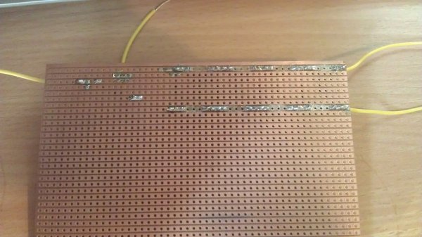
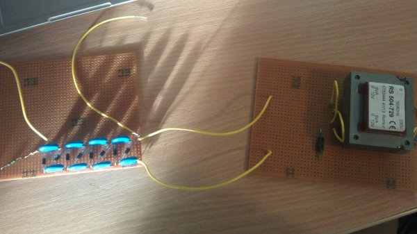
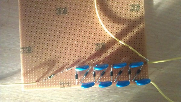
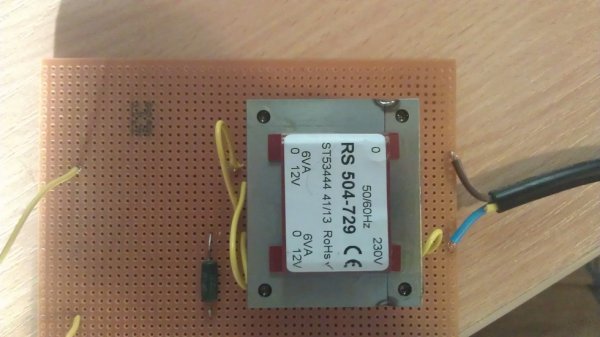
At the minute I am waiting for another transformer to use for isolation between the circuit and mains(UK mains). Meanwhile I'm using a transformer that is inputting 12V into a 4 stage cockcroft-Walton ladder/Cascade, which theoretically should give me 48V (give or take a couple of volts due to diode drop), however when the the fly wires come in close proximity I don't see any sparks. I want to make sure that the circuit works fully before upping the the voltage.
(When the transformer arrives the ladder should multiply the voltage to around 2.7kV).

If anyone could help me, it would be much appreciated.

P.s. I have attached to pictures to aid any suggestion.

Regards
James
 
  1. Post a schematic.
  2. Measure with a meter; trying to verify by arcing the output could damage the circuit, and 48 V is not much to cause a spark anyway. You may get one tiny spark then blow the diodes...
  3. I suspect you will see more arcs and sparks when the output is 2.7 kV due to all the extra copper around. I would cut the Cu away all around the junction points.


HTH - Don
 
The prototype board you are using is not prepared to accept such high voltages between close tracks, specially when you have solder spikes on them.
Perhaps you can optimize the layout to use it and coat the whole copper side with insulating epoxy or similar after finishing the board, but changing a component in the future will be a lot of work.
BTW, you should add some protection resistors in series with the transformer secondary when testing the device to avoid blowing it in case of malfunctioning. In my good days of DIY ESL's I tested these devices using a variac and slowly increasing the input voltage while measuring the HV. Remember 2700V is high voltage - you need an HV probe and it can hurt you!
 
Last edited:
That kind of board is good to test the circuit, but lousy for high voltage. High voltage can do weird things. You need lots of separation between circuits.

You might want to be able to adjust it too. Sound Lab used to put a potentiometer on the primary of the transformer, and had lots of Bias pot failures as a result. So I would consider putting the pot on the output side of the transformer, and likely a series resistance, so the entire secondary voltage is not simply dropped across the pot.
 
Sound Lab used to put a potentiometer on the primary of the transformer, and had lots of Bias pot failures as a result. So I would consider putting the pot on the output side of the transformer, and likely a series resistance, so the entire secondary voltage is not simply dropped across the pot.

Ralph,

Since long time SoundLab has been using an adjustable switching HV power supply, the adjust potentiometer is not in series with the HV module . The approach you refer - an L pad resistor type attenuator at the secondary is used in the Quads ESL's. We should remember that using a potentiometer for this purpose can be an hazardous problem for amateurs.
 

About us

  • What’s Best Forum is THE forum for high end audio, product reviews, advice and sharing experiences on the best of everything else. This is THE place where audiophiles and audio companies discuss vintage, contemporary and new audio products, music servers, music streamers, computer audio, digital-to-analog converters, turntables, phono stages, cartridges, reel-to-reel tape machines, speakers, headphones and tube and solid-state amplification. Founded in 2010 What’s Best Forum invites intelligent and courteous people of all interests and backgrounds to describe and discuss the best of everything. From beginners to life-long hobbyists to industry professionals, we enjoy learning about new things and meeting new people, and participating in spirited debates.

Quick Navigation

User Menu