@bonzo75: OK, thanks, I thought by your comments you were only (or primarily) interested in listening impressions and I don't really have any to offer that would mean anything (not current with high-end cables). If there is cable sensitivity, I would expect SS-SS to exhibit the least impact, then SS-V/V-SS, and finally V-V the most sensitive to the cable where SS = solid-state and V = valve (instead of "tube" seeing as how you are on the other side of the pond from me

). That is based on the typical impedances and of course YMMV with specific components and all that jazz.
Thank you for weighing in, Don. I appreciate it!
I, for one, like your posts whether they are technical or non-technical.
With respect to your comment about the passive filter, by "load" do you mean the amplifier which is receiving the high-pass signal? If that is the case then isn't the "load" the VTL with an input impedance of 130Kohm?
By "source" of the passive filter do you mean the output of the Io?
Thanks Ron.
Yes.
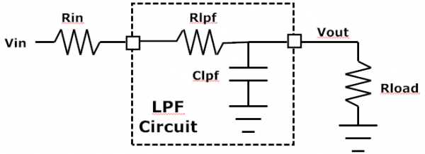
A passive filter to me means a simple RLC (resistor, inductor, capacitor) design with no active components. That means no buffers at its input or output to isolate the filter from whatever drives it (its source) and whatever it is driving (its load). Consider a simple single-pole LPF comprising a single RC as shown in the figure. A capacitor goes from infinite impedance at DC to a short at very high frequencies so that is what causes the frequency roll-off. The corner (roll-off) frequency is 1 / (2 * pi * Rlpf * Clpf) assumming the source (driving) impedance Rin is 0 ohms (an ideal voltage source) and the load impedance Rload is infinite (an open circuit). Aside: in the real world impedances are more than simple resistors but they are fine for this example.

The equation for the filter’s transfer function with ideal (0-ohm Rin) source and load (infinite Rload) is:
Vout/Vin = 1 / (1 + s*Rlpf*Clpf) where s is the complex frequency value:
s = jw = j*2*pi*f; w = freq in radians/s, f = freq in Hz, j = sqrt(-1)
Clearly if the source resistor is not 0 ohms, then the total series resistance is higher (Rin + Rlpf > Rlpf alone) and the corner frequency will drop. If the load resistance is not infinite it will do a couple of things: it will reduce (attenuate) the output because of the voltage divider formed by (Rin + Rlpf) and Rload, and it changes the frequency response. The equation when the load is finite (instead of infinite) is:
Vout/Vin = Rload / (Rlpf + Rload + s*Rlpf*Rload*Clpf)
If Rload is infinite this devolves to the same equation as above. The net result is that finite but high load impedance changes the gain (attenuation) and frequency of the LPF a little bit. Active buffers are designed to present a high impedance to the source (Vin) and low output impedance to the filter, and on the output presents a high-impedance load to the filter and low-impedance driving source to the next component in the chain. Without them, the LPF (or whatever type passive filter is used) is more sensitive to whatever drives and loads it. In the real world a decent passive filter will accommodate a pretty wide range of source and load impedances without significantly changing the filter’s frequency response.
HTH - Don


