Introducing Center Stage 2M

I think I misunderstood your question, originally. I can say without hesitation that the CS2M footers outperform the CS2. There is no question about it.
Hi Joe,
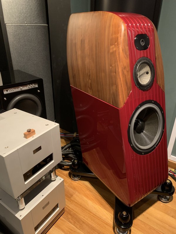
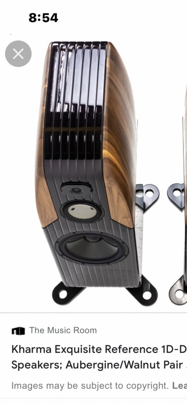
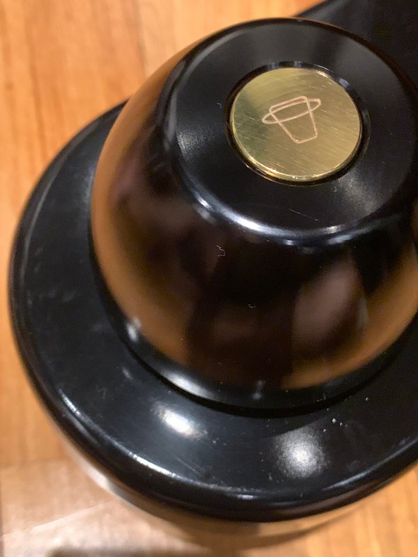
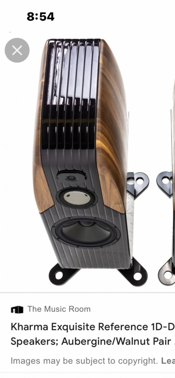
Interested to replace my Kharma Exquisite Reference footers with your CS2 LS 1.0. Kindly explain how to integrate the Kharma spikes to the CS2 LS 1.0 footers. Many thanks.367CD069-6006-4ED3-821C-D581FC7DF745.jpeg
 
Hi Joe,
Interested to replace my Kharma Exquisite Reference footers with your CS2 LS 1.0. Kindly explain how to integrate the Kharma spikes to the CS2 LS 1.0 footers. Many thanks.View attachment 95608
Reach out to Damon Von Schweikert as they distribute the LS version of the feet
 
Hi Joe,
Interested to replace my Kharma Exquisite Reference footers with your CS2 LS 1.0. Kindly explain how to integrate the Kharma spikes to the CS2 LS 1.0 footers. Many thanks.View attachment 95608
If I may Robert, I would be happy to assist with your question.

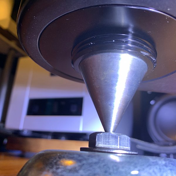
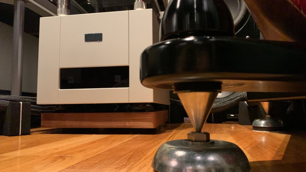
The CMS LS 1.0 would replace both the Kharma footer as well as the spike. For ease of use with your speakers, I advise either mounting them directly under the plinths or utilize the spike insert along with our titanium adapters. The second option is more secure but I'm noticing the scalloped recess of the plinth around the spike from this photo. Depending on diameter, this might inhibit full surface to surface contact with the top of the LS Footer. In which case I would advise bypassing the spike insert and simply place them just inside of that position for better contact.

The cylinder top diameter of the LS 1.0; the part that must be in surface to surface contact with the bottom of your speaker, is 60mm. This should help you decide how it will fit under your plinth.

This video may help illustrate what I'm trying to describe. Please feel free to contact me if you have any questions.
 
Last edited:
If I may Robert, I would be happy to assist with your question.

The CMS LS 1.0 would replace both the Kharma footer as well as the spike. For ease of use with your speakers, I advise either mounting them directly under the plinths or utilize the spike insert along with our titanium adapters. The second option is more secure but I'm noticing the scalloped recess of the plinth around the spike from this photo. Depending on diameter, this might inhibit full surface to surface contact with the top of the LS Footer. In which case I would advise bypassing the spike insert and simply place them just inside of that position for better contact.

The cylinder top diameter of the LS 1.0; the part that must be in surface to surface contact with the bottom of your speaker, is 60mm. This should help you decide how it will fit under your plinth.

This video may help illustrate what I'm trying to describe. Please feel free to contact me if you have any questions.

Reach out to Damon Von Schweikert as they distribute the LS version of the feet
Thanks Steve and Damon for your help.
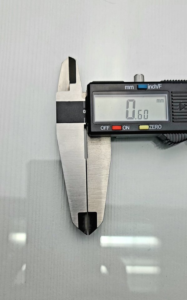
1) The spike threads diameter is 44mm and there is a 0.6 mm step up from the spike threads to the plinth so mounting directly under the plinth is not safe as the LS 1.0 would be group close together and stability will be an issue as speaker is 500lbs.
2) "utilize the spike insert along with our titanium adapters" kindly elaborate on this method.

Thanks, Robert
Dear Robert,

1 - I'm sorry but I'm confused by this statement. I would be very surprised if the threaded portion of the spike is 44mm in diameter On many speakers, they are M8 or M10 and sometimes 3.4" diameter, etc. And I don't understand what you mean by the 0.6mm step up. Is it possible for you to show with a picture and some notation?

2 - In the video at 1:57 you can see the image of the LS Footer with the titanium adapter installed about to be screwed up into the stock spike insert at the bottom of the speakers. We custom fabricate these titanium adapters to thread into the client's existing spike insert so that it can securely install while mounting surface to surface with the bottom of the speaker of the stock outriggers. If you like, I can make a quick video showing this.
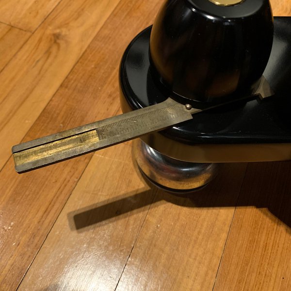
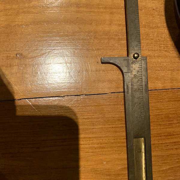
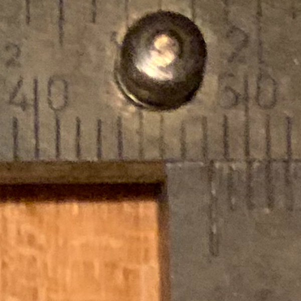
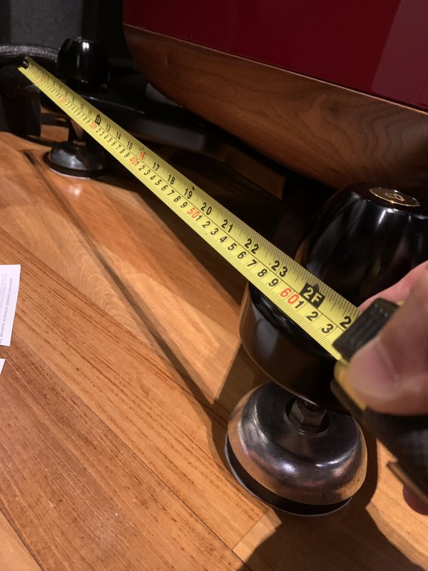
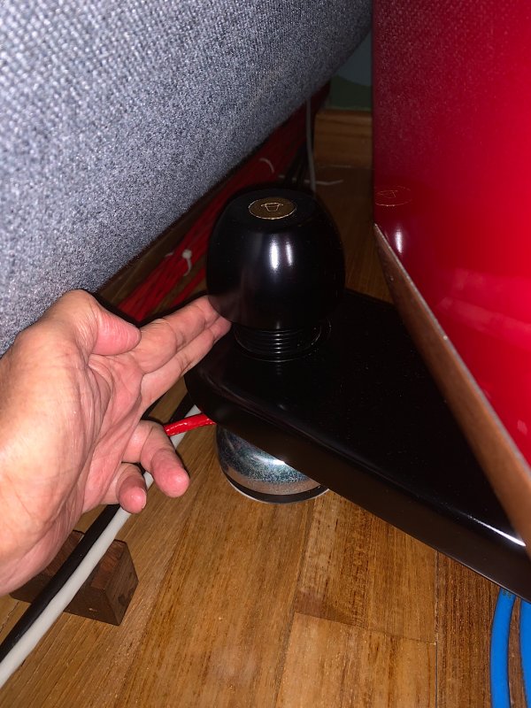
The threaded portion diameter is 48 mm as measured with a F caliper. There is a 70 mm diameter ring recess of 0.6 mm around the spikes threads. Looks like the spike insert is too big.
 

Attachments

  • 3500239C-50A7-40F6-B2DE-DF89FBC644EA.jpeg
    3500239C-50A7-40F6-B2DE-DF89FBC644EA.jpeg
    302.1 KB · Views: 12
  • 38621E48-3451-4002-8EFA-76D9A0D44B28.jpeg
    38621E48-3451-4002-8EFA-76D9A0D44B28.jpeg
    430.3 KB · Views: 9
  • 6BDEF561-4982-4A89-B2B9-E5E6BE5573E9.png
    6BDEF561-4982-4A89-B2B9-E5E6BE5573E9.png
    1.7 MB · Views: 10
  • AC278769-2B2C-45A2-B803-8109A27890D3.jpeg
    AC278769-2B2C-45A2-B803-8109A27890D3.jpeg
    267.5 KB · Views: 14
  • 1E00FD33-E2B1-4490-A350-E9AC799C54E0.jpeg
    1E00FD33-E2B1-4490-A350-E9AC799C54E0.jpeg
    565.7 KB · Views: 15
  • 996E4050-F456-4042-BE0A-0A6BE1AEE89A.jpeg
    996E4050-F456-4042-BE0A-0A6BE1AEE89A.jpeg
    213 KB · Views: 16
  • A11F0EFB-DF60-49EC-BDF6-7C1FF648037B.jpeg
    A11F0EFB-DF60-49EC-BDF6-7C1FF648037B.jpeg
    415.2 KB · Views: 13
The threaded portion diameter is 48 mm as measured with a F caliper. There is a 70 mm diameter ring recess of 0.6 mm around the spikes threads. Looks like the spike insert is too big.
Robert/Damon

I hope you don't mind me adding to the exchange. Pursuant to a joint agreement with VSA, CMS Manages the fabrication and assembly of LS products to ensure the highest quality standard is maintained for you. Damon and I both believe this is the best approach. The upside is that you get both minds working for you.

So, if I understand this, and please correct me if I have it wrong, there is a rather large threaded "hole" in the outrigger 48mm in diameter. The adapter coming out of the top of the LS 1.0 foot must mirror this diameter and thread pattern. Also, an "insert ring" must be fabricated to fit just above the LS 1.0 to fill the 70mm wide, 0.6mm deep indentation in order to make the bottom of the outrigger level.

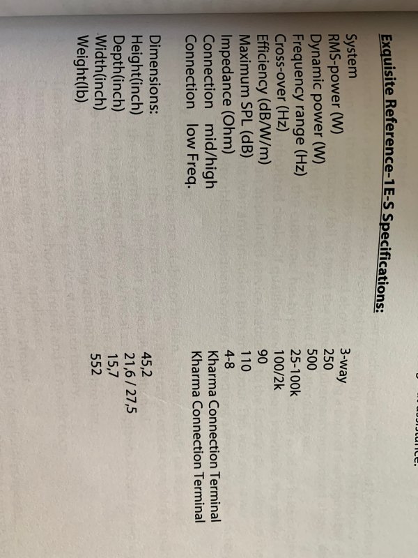
We need to confirm the adapter, but assuming fabrication is not an issue, all of this could be accomplished without affecting the performance of the LS 1.0 and we might even be able to go up to the LS 1.5 (see question below). In fact, I would guarantee significantly better performance for your loudspeakers using either LS foot. As a side bar, 552 lbs is far below the load tolerance of either foot.

I do have a question. What is the diameter of the outrigger outside-edge to outside-edge?
 
Robert,

Thanks for taking the time to provide these photos, I now understand the situation better and concur with Joe's solution. We can utilize your existing outriggers by fabricating an adapter.

That said, there are aspects about the outrigger assembly that I still have questions about.

I did an extensive search online and I can't find assembly instructions on the outriggers. It appears from the owner's manual that these come assembled from the factory.

First, how confident are we that the "ring recess" is only 0.6mm? Or is that simply the portion sitting proud of a thicker ring? I'm looking at our calipers and that's a very thin piece of metal if that is the case; especially if you wanted to thread it. Or does it just act as a beauty ring "washer?"

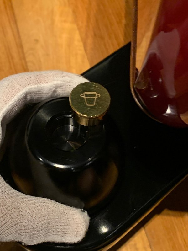
20220719_104021.jpgSecond, from the photos you've provided and what I could find online, it doesn't look like the shaft through the outrigger is threaded. Do you know if that's the case? If not, I "assume" it threads into the "cap" piece on top of the outrigger.

Prior to fabrication, we'll need to identify these details as well as thread pitch.
 
Damon/Joe,
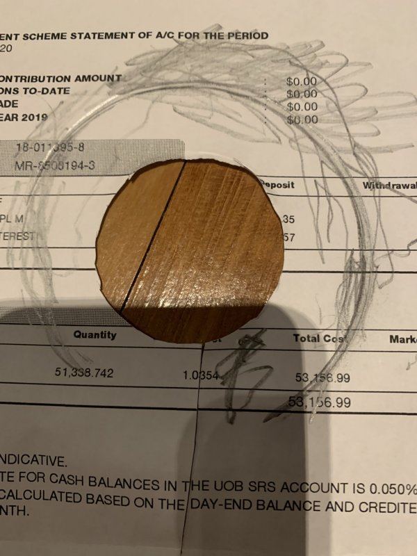
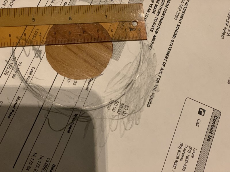
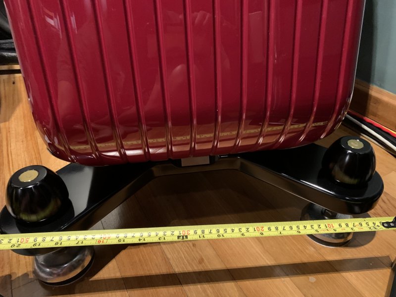
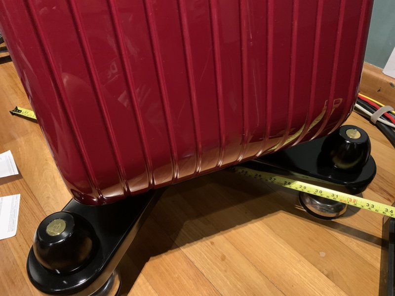
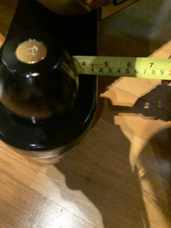
I traced the recess diameter approx 89 mm and not 70 mm. See photo with ruler. Outriggers front /center outside edge approx 53cm, side/center outside edge approx 63cm and diagonal outside edge approx 84cm.
The recess ring depth of 0.6mm was estimated previously by feeling with finger. Today I again run my finger’s tip around the recess and confirmed the recess depth is not even. The outrigger is 36mm thick and 113mm broad.
 

Attachments

  • E5276F70-FD46-4399-825A-E53020CB276E.jpeg
    E5276F70-FD46-4399-825A-E53020CB276E.jpeg
    466.5 KB · Views: 4
  • D28A5FB5-C734-46E9-A399-B74430F72F54.jpeg
    D28A5FB5-C734-46E9-A399-B74430F72F54.jpeg
    377.2 KB · Views: 3
  • E0256D25-8C82-486D-94FD-ED01D6022294.jpeg
    E0256D25-8C82-486D-94FD-ED01D6022294.jpeg
    717.2 KB · Views: 4
  • D01AC797-181C-495D-8776-540F1DFBB34B.jpeg
    D01AC797-181C-495D-8776-540F1DFBB34B.jpeg
    636.6 KB · Views: 4
  • 603C1966-88CA-4070-94F3-BC6E840F4FE5.jpeg
    603C1966-88CA-4070-94F3-BC6E840F4FE5.jpeg
    660.3 KB · Views: 5
  • 5A9F18E3-D455-4F41-A7EC-418FCDB6104F.jpeg
    5A9F18E3-D455-4F41-A7EC-418FCDB6104F.jpeg
    614.8 KB · Views: 5
  • E21EC3CE-C78A-499E-9672-9CB7F780CC5D.jpeg
    E21EC3CE-C78A-499E-9672-9CB7F780CC5D.jpeg
    392.5 KB · Views: 4
Damon/Joe,
I traced the recess diameter approx 89 mm and not 70 mm. See photo with ruler. Outriggers front /center outside edge approx 53cm, side/center outside edge approx 63cm and diagonal outside edge approx 84cm.
The recess ring depth of 0.6mm was estimated previously by feeling with finger. Today I again run my finger’s tip around the recess and confirmed the recess depth is not even. The outrigger is 36mm thick and 113mm broad.
Thank you for your excellent engagement. Your help is priceless.

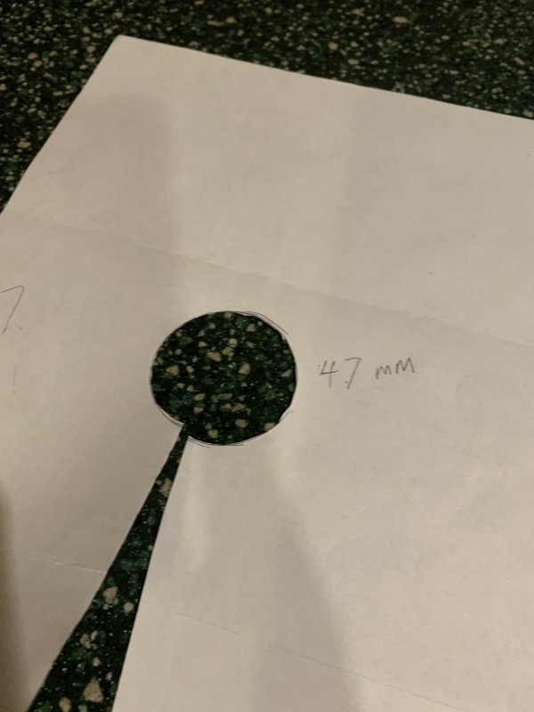
I am focused on 1/7, 3/7 and 7/7 of this photo series. If I see things clearly, we can fabricate a round 4.7mm thick plate to lay over the entire top surface of either the LS 1.5 or the LS 1.0 foot (you are a candidate for either) to provide a large flat contact area under the outrigger that would act as a transmission interface between the foot and the outrigger. The interface would drop over the connector through its slightly larger bored hole. The physical properties of the foot and the loudspeaker will transmit through the interface. The principle is the same as the outrigger itself. We can anodize the interface black and it will disappear entirely.

If you asked me for a recommendation as to which foot to use with a loudspeaker of this quality and an outrigger of this design (47mm inset shown in 1/2), I would suggest the 1.5 for performance and support. The mass of the loudspeaker is not an issue.

Damon, I look forward to your additional assessments.....
Joe,
I am not very clear of your recommendation. Can you elaborate it with a sketch.

This “Cap” is screw into the hole of the outrigger,
Thanks
 

Attachments

  • E34C0929-5EF5-4B5C-A4C5-A32553705057.jpeg
    E34C0929-5EF5-4B5C-A4C5-A32553705057.jpeg
    345.7 KB · Views: 11
  • 3FD3766C-2BC6-4974-9B91-905FF9F6CB79.jpeg
    3FD3766C-2BC6-4974-9B91-905FF9F6CB79.jpeg
    448.8 KB · Views: 10
  • AC08D298-933A-4FEC-9A83-26700E1E6987.jpeg
    AC08D298-933A-4FEC-9A83-26700E1E6987.jpeg
    213 KB · Views: 10
Joe,
I am not very clear of your recommendation. Can you elaborate it with a sketch.

This “Cap” is screw into the hole of the outrigger,
Thanks
Sorry for the late reply. The spike appears to be thread in photo 4/7 in post #366. This indicates that the hole in the outrigger is machined to receive the thread and allow it to pass through upward and into the cap. My assumption is (correct me if I am wrong) the cap screws down onto the connector protruding upward from the spike through the threaded hole in the outrigger. If this is correct, we would duplicate the thread and pitch of the spike connector for the LS foot. Make better sense now? Please advise.
 
Sorry for the late reply. The spike appears to be thread in photo 4/7 in post #366. This indicates that the hole in the outrigger is machined to receive the thread and allow it to pass through upward and into the cap. My assumption is (correct me if I am wrong) the cap screws down onto the connector protruding upward from the spike through the threaded hole in the outrigger. If this is correct, we would duplicate the thread and pitch of the spike connector for the LS foot. Make better sense now? Please advise.
According to the retired employee of the store where I bought the speakers 10 years ago, the cap and spike is fabricated from on block of metal (material cannot be confirmed).
 
According to the retired employee of the store where I bought the speakers 10 years ago, the cap and spike is fabricated from on block of metal (material cannot be confirmed).
Honestly, this is fairly common. The vertical stanchions, feet and caps of our racks are machined from the same bar of metal. Many components of the LS feet are machined from common bars of metal. This is an interesting piece of information,, but just as honestly, this is not important to our conversation.

But do you see an issue I need to consider. Perhaps, I am missing something. Please let me know.
 
Joe/Damon,
I saw this information in AudioShark Forum
"Center Stage2 LS 1.5 next to a Center Stage2 1.5 contracted and extended. Cylinder diameter: 3” (76mm), spike cup diameter: 5” (127mm), contracted: 3.1” (79mm), extended: 3.8” (97mm). Center Stage2 LS 1.0 (not shown) cylinder diameter: 2.375” (60mm), spike cup diameter: 4” (102mm) contracted: 2.7” (69mm), extended: 3.4” (86mm)"

The contracted dimension of LS 1.0 of 2.7" with the added adapter plate thickness is too high for my speakers setup. I measured the "gap" between the floor and the bottom of the outrigger at the rear spike/footer of the left speaker is only 2.5". The 4 "gaps" dimension are different so as to level the speaker front to back and side to side.

Thanks
 

Attachments

  • F007AC01-AB24-403A-A9B8-C1EC3B100AAF.jpeg
    F007AC01-AB24-403A-A9B8-C1EC3B100AAF.jpeg
    536.6 KB · Views: 8
  • EA3811E4-52C1-45A2-88E3-051947ADBE4F.jpeg
    EA3811E4-52C1-45A2-88E3-051947ADBE4F.jpeg
    363.6 KB · Views: 8
Joe/Damon,
I saw this information in AudioShark Forum
"Center Stage2 LS 1.5 next to a Center Stage2 1.5 contracted and extended. Cylinder diameter: 3” (76mm), spike cup diameter: 5” (127mm), contracted: 3.1” (79mm), extended: 3.8” (97mm). Center Stage2 LS 1.0 (not shown) cylinder diameter: 2.375” (60mm), spike cup diameter: 4” (102mm) contracted: 2.7” (69mm), extended: 3.4” (86mm)"

The contracted dimension of LS 1.0 of 2.7" with the added adapter plate thickness is too high for my speakers setup. I measured the "gap" between the floor and the bottom of the outrigger at the rear spike/footer of the left speaker is only 2.5". The 4 "gaps" dimension are different so as to level the speaker front to back and side to side.

Thanks
I keep on apologizing for late replies. So, I'll do it again. Much going on. Back to business.....

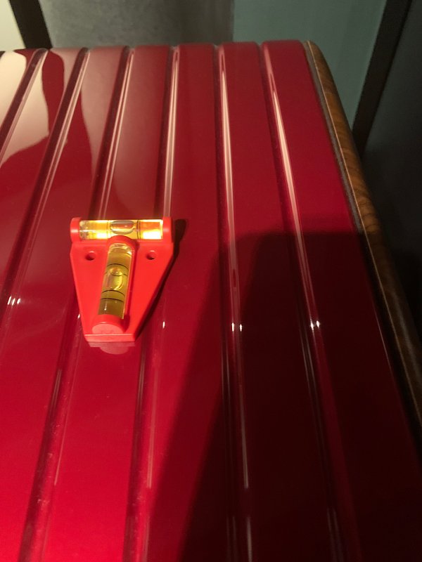
I think I understand your concern, but let me know if I miss something. The LS feet are designed to allow you to level the speaker. After the foot is installed you adjust height by turning the dial on the bottom of the foot. The dial is 4" in diameter on the LS 1.0 and 5" in diameter on the LS 1.5. I offer this to assure you that leveling the speaker will not be a problem and to let you know that LS feet level through an internal mechanism located at the bottom of the foot. This is much different than the mechanism you have with your current feet. Correct if I am wrong, but it appears that your current feet level by twisting the spike up or down until you get the bubble centered as you have shown and then locking them in. Honestly, the LS feet are much more sophisticated, but please don't read this as a criticism of your current feet. To summarize, the "gaps" which are created by your current leveling process are not relevant with LS feet. But it is very important that you bring this up as it needs to be addressed, as we just did. The height of the tweeter will not be a concern because the LS feet allow the loudspeaker to better integrate the drivers including the tweeter. And, the speaker can be raked using the LS feet height adjustments.

I hope this helps.
 
Hi Joe/ Damon,
I am concern that to install the LS 1.0 feet, the 4 mounting points of the outrigger need to be jacked up higher as the contracted dimension of the LS 1.0 plus the thickness of the adapter plate is greater than the "gap" between the floor and the bottom of the outrigger of my speakers. Changing the height of the tweeter and the mid-range driver to a higher position will definitely change the overall presentation. For this reason I apply the KISS principle.

Many thanks to know your great products.
I'm a little late to this discussion but let me add my $0.02

I have my entire front and back end components all sitting on CS2M footers (76 in total) which sit on CMS racks. I have tall Wilson X2 Series ll speakers that stand at least 6 feet tall. I had opportunity to audition both the LS 1.0 and the LS 1.5 under my speakers. If you are familiar with Wilson speakers they have the ability to time align the upper and lower midrange module as well as the tweeter module, all based on distance from tweeter to tweeter as well as distance from tweeter to listener's ear. Like you I agonized about what effect elevating the speaker would have on the ultimate position of the upper modules and whether an adjustment would be needed as these 3 drivers would now sit about 1.5" higher than when the speakers were spiked. I can confirm to you that the overall sound was not only better due to the LS footers but there was zero difference in the sound. IOW there was no need to make any changes in the upper modules. Not only do I feel comfortable stating this but my findings were corroborated by Damon and Leif who have been to my home countless times and lately have been helping me with a totally new way to set up my Wilson speakers such that none of the Wilson algorithm are used. At their recent visit we discussed whether any change in the upper modules was necessary Neither Leif, Damon or myself felt this was necessary. I have now had the LS 1.5's under my speakers for almost 2 years and I have said before that the overall sonic benefit of a pair of LS footers is as good or better than all front and back end gear being supported by CS2M footers (which BTW are IMO the best version Joe has released to date)

I am a firm believer as well in the KISS technique. However in summary the addition of the LS footers under my speakers was a huge uptick with no negatives as a result of elevating the drivers.

HTH
Hi Steve,
Many thanks to you for your input to this discussion. You have a fantastic sound system with all the components resting on the CS2M footers and LS 1.5 under your Wilson X2 Series II speakers. Love to hear your system.
Love your statement " the overall sonic benefit of a pair of LS footers is as good or better than all front and back end gear being supported by CS2M footers (which BTW are IMO the best version Joe has released to date)." This statement of yours is a confidence booster for any customer looking at the LS footers including myself.
My room width of 12 feet is small and very sensitive to the position of these speakers. Considerable amount of efforts were put in to finally set the speakers in the present position. I have been listening to the presentation of these speakers in this position for the last 12 years and very happy with it. Having to increase the height of the drivers of the speakers with the installation of the LS footers might not be good so the KISS technique is best for me. IMHO the Wilson speakers are more forgiving with the flexibility of adjustment to the drivers.
Presently there is no CSM dealer in my location, however in the future when the opportunity to audition arise, I love to audition the LS 1.0 and LS 1.5 under my speakers.
 

About us

  • What’s Best Forum is THE forum for high end audio, product reviews, advice and sharing experiences on the best of everything else. This is THE place where audiophiles and audio companies discuss vintage, contemporary and new audio products, music servers, music streamers, computer audio, digital-to-analog converters, turntables, phono stages, cartridges, reel-to-reel tape machines, speakers, headphones and tube and solid-state amplification. Founded in 2010 What’s Best Forum invites intelligent and courteous people of all interests and backgrounds to describe and discuss the best of everything. From beginners to life-long hobbyists to industry professionals, we enjoy learning about new things and meeting new people, and participating in spirited debates.

Quick Navigation

User Menu