Selection of digital cables BNC 75 Ohm.

Amir

Well-Known Member
May 3, 2021
856
644
160
45
Tehran, Iran
www.amiraudio.com
Can we know what is exactly meant by this confusing sentence?
yes sure,
in analog sound signal transfer the speed of signal is not high as you know the frequency bandwidths of sound signal is less than 20khz so the speed of signal is so far less than the speed of light and this means there is no signal phase shift (time delay) across the Interconnect so the signal does not act like wave. in digital signal transfer the square wave of digital signal has more than 1Mhz bandwidths so the signal acts as wave .
for right wave signal transfer you need to 100% fix the impedance of line across the interconnect. this problem can not solve by handmade cables in this market and needs a precision machine for producing digital cable.
most audio companies produce handmade digital cables and their impedance is not constant across the line but the Acrolink impedance is 100% accurate.
in electronics when the frequency goes up then all circuits does not act like simple electronics model and even an interconnect act like a waveguide.
if you look at the BNC vs RCA connectors at the end of digital cables you will see the impedance of BNC is correct (75ohm) and the impedance of RCA is not match to 75ohm coaxial cable, it means even an small connector can change the lmpedance.
 
  • Like
Reactions: Republicoftexas69

InfigoAudio

Industry Expert
Jun 14, 2022
64
75
25
57
Kelowna, BC, Canada
www.infigoaudio.com
in analog sound signal transfer the speed of signal is not high as you know the frequency bandwidths of sound signal is less than 20khz so the speed of signal is so far less than the speed of light and this means there is no signal phase shift (time delay) across the Interconnect so the signal does not act like wave. in digital signal transfer the square wave of digital signal has more than 1Mhz bandwidths so the signal acts as wave .

I think the correct way to look at this is looking at the wavelength of the signal vs the length of the cable to determine how much the cable acts as a transmission line.
Analog sound signals travel at the same speed through cables as their digital versions.
Usually one starts looking already at a quarter of the wavelength for impedance matching to avoid reflections that lead to signal degradation.
20 kHz however has a wavelength in cables of over 10 km (https://www.everythingrf.com/rf-calculators/frequency-to-wavelength) so it is safe to say the cable is only acting as a transmission line in a negligible way.
Even so, for instance Dartzeel uses impedance matching of cabling for audio bandwidth signals with success.

The wavelength of digital signals is much shorter so it becomes more important to avoid reflections. Even though in S/PDIF the wavelength is still relatively long compared to cable length (> 100m) impedance matching is critical here because the sampling clock needs to be derived from this signal with as low as possible jitter caused by reflections.

Needless to say the importance of correct impedance is vital in high speed connections such as USB or Ethernet or masterclock signals such as referenced in the OP.

Cheers, Hans.
 
Last edited:
  • Like
Reactions: Republicoftexas69

microstrip

VIP/Donor
May 30, 2010
20,807
4,702
2,790
Portugal
yes sure,
in analog sound signal transfer the speed of signal is not high as you know the frequency bandwidths of sound signal is less than 20khz so the speed of signal is so far less than the speed of light and this means there is no signal phase shift (time delay) across the Interconnect so the signal does not act like wave. in digital signal transfer the square wave of digital signal has more than 1Mhz bandwidths so the signal acts as wave .
for right wave signal transfer you need to 100% fix the impedance of line across the interconnect. this problem can not solve by handmade cables in this market and needs a precision machine for producing digital cable.
most audio companies produce handmade digital cables and their impedance is not constant across the line but the Acrolink impedance is 100% accurate.
in electronics when the frequency goes up then all circuits does not act like simple electronics model and even an interconnect act like a waveguide.
if you look at the BNC vs RCA connectors at the end of digital cables you will see the impedance of BNC is correct (75ohm) and the impedance of RCA is not match to 75ohm coaxial cable, it means even an small connector can change the lmpedance.

Again, "impedance is not constant across the line " does not mean anything understandable. What is "across the line" or "across the interconnect"? Do you realize that 100% accurate is something that does not exist?

Well, unless you give us some accurate data this is just coffee talk mixed with your improperly stated cable impedance matching theory - all electronic engineering students study it and do practical work on it. But it seems you do not understand it.
 
  • Like
Reactions: AndrewChen

justubes

Well-Known Member
Aug 10, 2015
211
102
273
Amir, i can only think of a handful for true 50/75 ohm high end custom produced digital cable.

They like you said have to be very accurately machine made in tight tolerances only acheivable in coaxial construction.

The brands that i can think of, Acorlink (oem - Esoteric rebranded), Black cat, Nordost and Shunyata, with many others handmade or small production are just twisted pairs which will not be able to acheive this impedance.

Some others use industral coaxial and put them in a sleve.

You have more issues with higher frequencies, like clocking in 10Mhz.

For many, transport to dac at 44khz'48Khz many not be nearly as critical, In any case spdif, even if upsampled, the protocol only supports only up to 192khz bandwidth.

I only look at coaxial types for clocking, simple scope test can show how a square wave resembles mount everest when impedence is not maintained.
 
  • Like
Reactions: Republicoftexas69

Amir

Well-Known Member
May 3, 2021
856
644
160
45
Tehran, Iran
www.amiraudio.com
Again, "impedance is not constant across the line " does not mean anything understandable. What is "across the line" or "across the interconnect"? Do you realize that 100% accurate is something that does not exist?

Well, unless you give us some accurate data this is just coffee talk mixed with your improperly stated cable impedance matching theory - all electronic engineering students study it and do practical work on it. But it seems you do not understand it.
The Impedance across the line is described in electromagnetic books and you can read it in the electromagnetic books.
 
  • Like
Reactions: Republicoftexas69

Amir

Well-Known Member
May 3, 2021
856
644
160
45
Tehran, Iran
www.amiraudio.com
Amir, i can only think of a handful for true 50/75 ohm high end custom produced digital cable.

They like you said have to be very accurately machine made in tight tolerances only acheivable in coaxial construction.

The brands that i can think of, Acorlink (oem - Esoteric rebranded), Black cat, Nordost and Shunyata, with many others handmade or small production are just twisted pairs which will not be able to acheive this impedance.

Some others use industral coaxial and put them in a sleve.

You have more issues with higher frequencies, like clocking in 10Mhz.

For many, transport to dac at 44khz'48Khz many not be nearly as critical, In any case spdif, even if upsampled, the protocol only supports only up to 192khz bandwidth.

I only look at coaxial types for clocking, simple scope test can show how a square wave resembles mount everest when impedence is not maintained.
Most companies have both coaxial and twisted pair if I am not mistaken.
buying over 1.5m cables (44.1khz CD) can help to decrease the back wave effect on the source.
 
  • Like
Reactions: Republicoftexas69

microstrip

VIP/Donor
May 30, 2010
20,807
4,702
2,790
Portugal
The Impedance across the line is described in electromagnetic books and you can read it in the electromagnetic books.

Yes, unfortunately the electromagnetic books just address the very basic theory and do not debate the reality of the caracteristic impedance. Your inability to deal with any question and just parroting promotional literature without supplying data makes this a dogmatic useless advertising session.
 

microstrip

VIP/Donor
May 30, 2010
20,807
4,702
2,790
Portugal
Amir, i can only think of a handful for true 50/75 ohm high end custom produced digital cable.

They like you said have to be very accurately machine made in tight tolerances only acheivable in coaxial construction.

The brands that i can think of, Acorlink (oem - Esoteric rebranded), Black cat, Nordost and Shunyata, with many others handmade or small production are just twisted pairs which will not be able to acheive this impedance.

Some others use industral coaxial and put them in a sleve.

You have more issues with higher frequencies, like clocking in 10Mhz.

For many, transport to dac at 44khz'48Khz many not be nearly as critical, In any case spdif, even if upsampled, the protocol only supports only up to 192khz bandwidth.

I only look at coaxial types for clocking, simple scope test can show how a square wave resembles mount everest when impedence is not maintained.

You are admitting that source and input impedance are ideal resistors of exact nominal value. Reality is quite different - it is why concerning digital cables experience and listening is needed.

Just see the extreme WADAX case where these aspects are tuned by the user to his preference.

Long ago a few friends and I owned the Forsell Airbearing CD transport and matching DAC. We tried many SPDIF BNC cables, even extremely accurate ones - we were at the golden age of digital cable experimentation - but no one sounded as good as the horrible Forsell supplied cable - an 8 mm thick cooper pipe with two twisted solid core thin wires.

BTW, if accuracy was the only important factor people would just have to fine tune the output and input impedances by ear!
 

Amir

Well-Known Member
May 3, 2021
856
644
160
45
Tehran, Iran
www.amiraudio.com
Yes, unfortunately the electromagnetic books just address the very basic theory and do not debate the reality of the caracteristic impedance. Your inability to deal with any question and just parroting promotional literature without supplying data makes this a dogmatic useless advertising session.
Absolutely Not , electromagnetic books (like david cheng) fully describe the impedance of line by solving maxwell's equations for both coaxial and twisted pair cables and the problem is your limited knowledge about electronics does not allow you to understand this subject.
When you can not understand my comments then it is your problem not mine.

I have no interest to answer your questions any more.
 
  • Like
Reactions: Republicoftexas69

microstrip

VIP/Donor
May 30, 2010
20,807
4,702
2,790
Portugal
Absolutely Not , electromagnetic books (like david cheng) fully describe the impedance of line by solving maxwell's equations for both coaxial and twisted pair cables and the problem is your limited knowledge about electronics does not allow you to understand this subject.

You must be joking ...

When you can not understand my comments then it is your problem not mine.

I have no interest to answer your questions any more.

Neither have I . But our readers deserve to know you are a real joke on these matters.
 
  • Angry
Reactions: Republicoftexas69

Republicoftexas69

Well-Known Member
You must be joking ...


Neither have I . But our readers deserve to know you are a real joke on these matters.
Clearly you have an ax to grind, I enjoy reading all points of view and your snark is really uncalled for. I understood Amir's answer, you have made it personal now. Show some restraint.
 

Amir

Well-Known Member
May 3, 2021
856
644
160
45
Tehran, Iran
www.amiraudio.com
The real joke is the action of morons when they do not undrestand a subject.


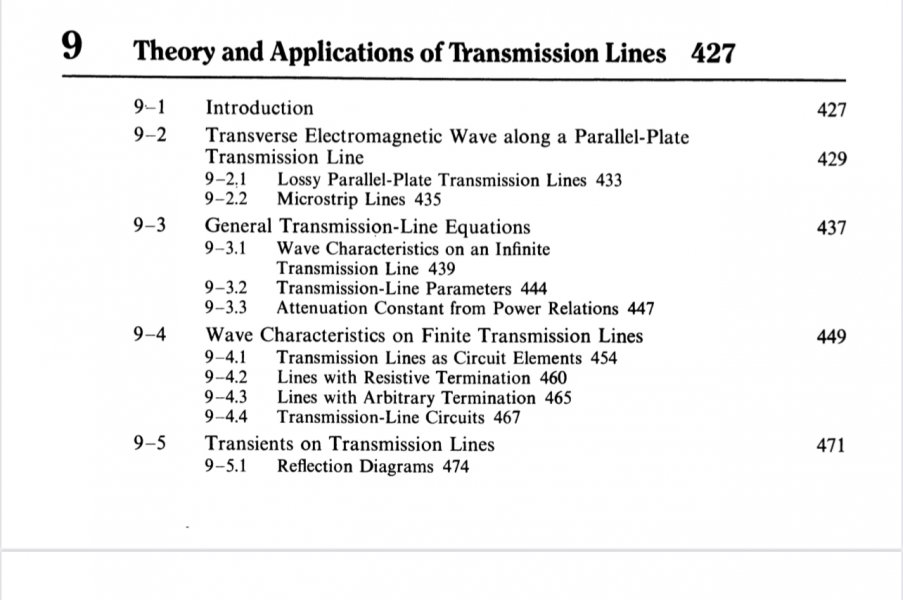
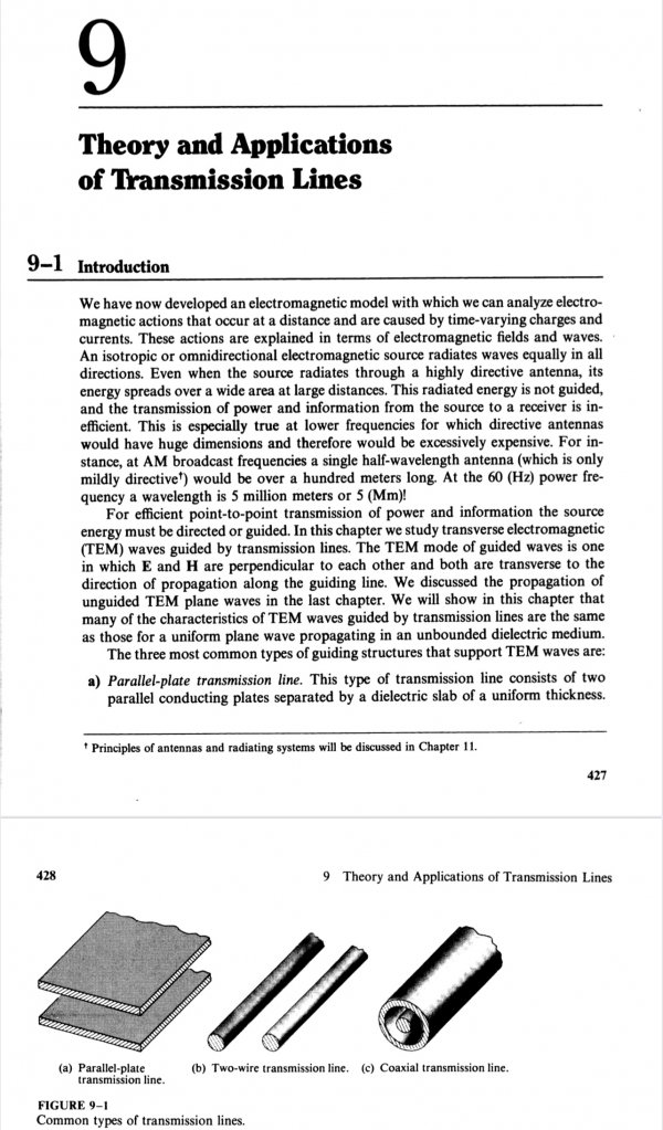
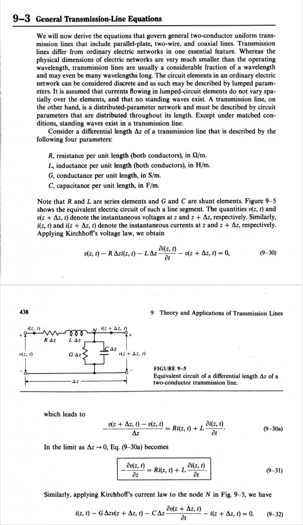
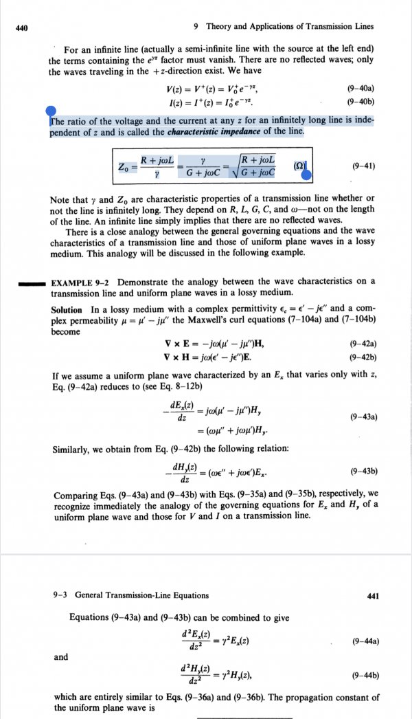
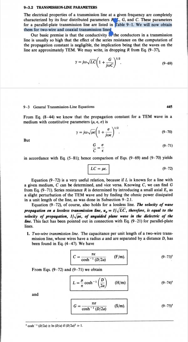
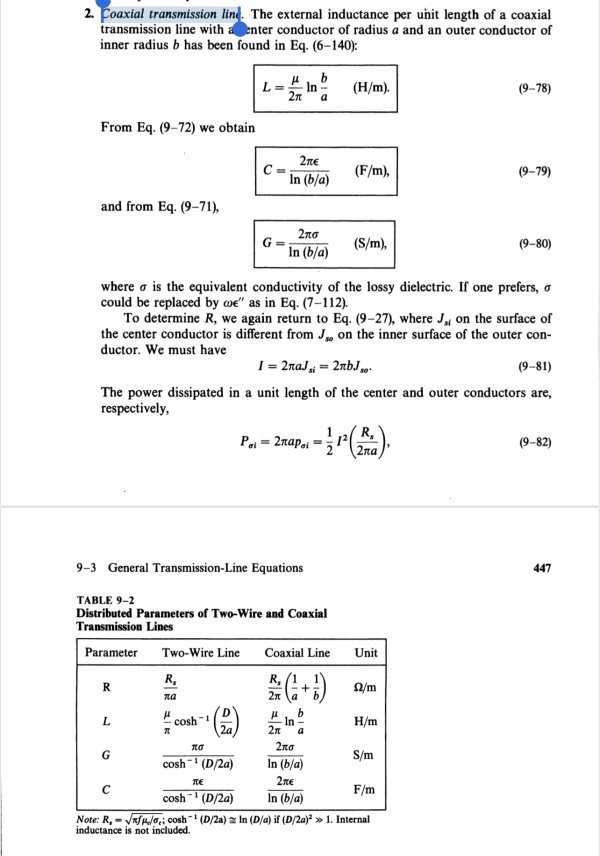
these pictures are from chapter 9 of cheng's Book :

IMG_5270.jpeg
Starts from Page 427
IMG_5271.jpeg

The equations :
IMG_5272.jpeg

The ratio of the voltage and the current at any z for an infinitely long line is inde- pendent of z and is called the characteristic impedance of the line.

IMG_5273.jpeg

Table 9-1. We will now obtain them for two-wire a n d coaxial transmission lines.

IMG_5275.jpeg
The coaxial parameters :

IMG_5276.jpeg
 
  • Like
Reactions: Republicoftexas69

microstrip

VIP/Donor
May 30, 2010
20,807
4,702
2,790
Portugal
The real joke is the action of morons when they do not undrestand a subject.


these pictures are from chapter 9 of cheng's Book :

View attachment 113040
Starts from Page 427
View attachment 113041

The equations :
View attachment 113042

The ratio of the voltage and the current at any z for an infinitely long line is inde- pendent of z and is called the characteristic impedance of the line.

View attachment 113043

Table 9-1. We will now obtain them for two-wire a n d coaxial transmission lines.

View attachment 113045
The coaxial parameters :

View attachment 113046

Thanks - at some time in my professional life I had to teach EM, Maxwell equations and equations similar to those you display to my students. I even assembled an experiment to study the propagation velocity and characteristic impedance of cables.

You are just trying to create confusion with basic mathematical and physical theory to dazzle our members that are not experts in physics. Bye.
 

Amir

Well-Known Member
May 3, 2021
856
644
160
45
Tehran, Iran
www.amiraudio.com
Page 441 and 442 and 443 describe the distortionless line and the important key is the cable parameters (R, L, G, C) across the line should be constant.
 
  • Like
Reactions: Republicoftexas69

Amir

Well-Known Member
May 3, 2021
856
644
160
45
Tehran, Iran
www.amiraudio.com
Thanks - at some time in my professional life I had to teach EM, Maxwell equations and equations similar to those you display to my students. I even assembled an experiment to study the propagation velocity and characteristic impedance of cables.

You are just trying to create confusion with basic mathematical and physical theory to dazzle our members that are not experts in physics. Bye.

those are not confusion, those are from the university reference electromagnetic book (d.cheng) .
If you can not understand please excuse WBF members and leave This discussion.

Goodbye forever
 

About us

  • What’s Best Forum is THE forum for high end audio, product reviews, advice and sharing experiences on the best of everything else. This is THE place where audiophiles and audio companies discuss vintage, contemporary and new audio products, music servers, music streamers, computer audio, digital-to-analog converters, turntables, phono stages, cartridges, reel-to-reel tape machines, speakers, headphones and tube and solid-state amplification. Founded in 2010 What’s Best Forum invites intelligent and courteous people of all interests and backgrounds to describe and discuss the best of everything. From beginners to life-long hobbyists to industry professionals, we enjoy learning about new things and meeting new people, and participating in spirited debates.

Quick Navigation

User Menu

Steve Williams
Site Founder | Site Owner | Administrator
Ron Resnick
Site Co-Owner | Administrator
Julian (The Fixer)
Website Build | Marketing Managersing