ARC SP-6A Tube Preamp

Are the protection diodes D19 and DZ15 OK?
What is the Voltage on the cathodes of the 12BH7?
BTW just because a tube is new is not saying its a good tube.
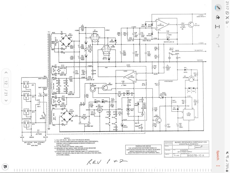
These are the voltages around V7 and V8, the 12BH7 and the ECC83 in the PSU.

V7 - 12BH7
1 - 668v (raw supply about 500mV of ripple on it)
2 - 357v
3 - 398v
4 - 398v (floating heater supply)
5 - 398v (floating heater supply)
6 - 668v, as Pin 1
7 - 357v, as Pin 2
8 - 398v, as Pin 3
9 - 398v (floating heater)

V8 - ECC83
1 - 355v +/- 0.2v
2 - 6.47v (from output of U2)
3 - 10.2v (from ZD10)
4 - heater supply
5 - heater supply
6 - 355v +/- 0.2v
7 - 6.47v (from output of U2)
8 - 10.2v (from ZD10)
9 - Gnd
 
Apologies for being stupid, but wouldn't I expect to have the heater pins on the 12BH7 "floating" at the B2+ HT voltage? I am measuring 398V wrt gnd on each of the heater pins, 398V is what the 402V B2+ is struggling to get to.
The UfKmax shows the voltage at which the filament/cathode insulation still "holds out": to reduce the heater hum, the level of the heater voltage can be set to a potential above or below that of ground - this is done by using a voltage divider between the operating voltage and ground. The resistors in series between the cathode and ground should not exceed 20 kΩ in total.
This value is in every data sheet of a tube. In your case, 400 volts are tapped at the cathode but the heater is 6.3 volts, the difference would be ~393 volts. This is too high a value for 12bh7a, the max permissible difference would be 200 volts, so the difference was reduced with the help of the voltage divider to B+.


I tried today adding a local RC network to the HT of the first two valves in the line stage, to lower the impedance of the PSU. The 6DJ8 in the line stage is powered by a separate PCB track for its HT and I didn't want to start cutting tracks.

View attachment 143923

Anyway, with the RC in place and the 6DJ8 out of socket the voltage after the anode resistors for the Line stage ECC83's stabilised and stopped wandering, but the HT voltage stayed at 398V. Putting the 6DJ8 back into the line stage, remember that its HT bypasses the local RC network, made the ECC83's anode voltage begin to oscillate as before. And again the HT stayed at 398V.
When the b+ voltage /current oscillates, it sounds like" motorboating" to me, which means that the supply voltage of the individual amplifier stages is not sufficiently decoupled from each other. For example, the resistance between the filter capacitors is too small. I'm not an expert on regulating operating voltage and current. In itself it is a good thing to add an additional RC filter. C17 200uf after ecc83 ok cappacity/low esr?

Previously I had replaced ZD15 and D19, and D13 D15 with new parts.

Just for completeness this is the PSU schematic for the one I'm working on.

View attachment 143921
My order from Mouser included every component of the PSU apart from the 2N6316 and the MC7824CK.

I'm really grateful for your help, but the PSU for the SP-8 I find particularly baffling :)
 
Last edited:
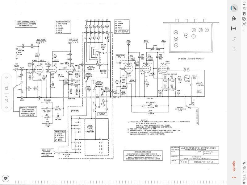
for a better understanding from the manual the schematicsScreenshot_20250118-211735_Write on PDF.jpgScreenshot_20250118-211800_Write on PDF.jpg

I would re-solder all soldering points on the PSU, especially those that are discolored from heat. Clean the tube sockets and replace them if necessary. Good luck
 
Last edited:
These are the voltages around V7 and V8, the 12BH7 and the ECC83 in the PSU.

V7 - 12BH7
1 - 668v (raw supply about 500mV of ripple on it)
2 - 357v
3 - 398v
4 - 398v (floating heater supply)
5 - 398v (floating heater supply)
6 - 668v, as Pin 1
7 - 357v, as Pin 2
8 - 398v, as Pin 3
9 - 398v (floating heater)

V8 - ECC83
1 - 355v +/- 0.2v
2 - 6.47v (from output of U2)
3 - 10.2v (from ZD10)
4 - heater supply
5 - heater supply
6 - 355v +/- 0.2v
7 - 6.47v (from output of U2)
8 - 10.2v (from ZD10)
9 - Gnd
668 volt is high normaly ~630 volt.
Two things can happend
1. False tap primary side main trafo for your voltage.
2. the main transformer has a winding fault, perhaps caused by a short circuit. This would explain the fluctuation in voltage at full load when all tubes in. AC output 450 Volt
 
668 volt is high normaly ~630 volt.
Two things can happend
1. False tap primary side main trafo for your voltage.
2. the main transformer has a winding fault, perhaps caused by a short circuit. This would explain the fluctuation in voltage at full load when all tubes in. AC output 450 Volt
From what I can see, but I will double check the primary side is wired for 240VAC, but my house voltage is always higher, 245-250VAC normally.

The fluctuations are only after the anode resistors and only on the line stage side...and with a little local RC the fluctuations stop, but the B2+ HT doesn't rise to 402V...

Is there a way to test the transformer for a short?

I did a quick check, +I've to CT and -ive to CT and both read 343V after the diodes.
 
Last edited:
From what I can see, but I will double check the primary side is wired for 240VAC, but my house voltage is always higher, 245-250VAC normally.

The fluctuations are only after the anode resistors and only on the line stage side...and with a little local RC the fluctuations stop, but the B2+ HT doesn't rise to 402V...

Is there a way to test the transformer for a short?

I did a quick check, +I've to CT and -ive to CT and both read 343V after the diodes.
My goal is to completely rule out this error; it rarely happens but it is possible.

surge current test, you disconnect both sides of the transformer (primary 240ac and secondary 450volt. Connect an oscilloscope to the secondary side. Add a 10uf capacitor, charge this to 5 volts and watch what happens on the oscilloscope. If you see a fading sine wave, the transformer is OK. If you only see one pulse, the transformer has a short circuit between turns. This can mean that you are getting too high an output voltage and at load (current) cannot maintain a constant voltage. Unfortunately, I only have a video in German but pictures say more than 1000 words.

P.S
The older Audio Research versions only have 220 volt tap, that would explain the high voltage. Which version do you have?newer version shematics 20250119_131731.jpg
 
Last edited:
I'm really grateful for your help, but the PSU for the SP-8 I find particularly baffling :)
It does seem overly complex.
Is the 24V regulator running properly?
. the main transformer has a winding fault, perhaps caused by a short circuit. This would explain the fluctuation in voltage at full load when all tubes in. AC output 450 Volt
Hmm... It does seem prudent to test the transformer!
The opamp U2 seems to be there only to amplify high frequency noise and apply it as feedback via the 12AX7 to the 12BH7. Am I interpreting this correctly? It is supplied by the 24V regulator. I would be testing that regulator to make sure its OK- any instability on its part could mess with the DC Voltage on the grids of the 12AX7.
 
My goal is to completely rule out this error; it rarely happens but it is possible.

surge current test, you disconnect both sides of the transformer (primary 240ac and secondary 450volt. Connect an oscilloscope to the secondary side. Add a 10uf capacitor, charge this to 5 volts and watch what happens on the oscilloscope. If you see a fading sine wave, the transformer is OK. If you only see one pulse, the transformer has a short circuit between turns. This can mean that you are getting too high an output voltage and at load (current) cannot maintain a constant voltage. Unfortunately, I only have a video in German but pictures say more than 1000 words.

P.S
The older Audio Research versions only have 220 volt tap, that would explain the high voltage. Which version do you have?newer version shematics View attachment 144014
That's very interesting, I shall give it a go and report back.
 
  • Like
Reactions: DasguteOhr
It does seem overly complex.
Is the 24V regulator running properly?

Hmm... It does seem prudent to test the transformer!
The opamp U2 seems to be there only to amplify high frequency noise and apply it as feedback via the 12AX7 to the 12BH7. Am I interpreting this correctly? It is supplied by the 24V regulator. I would be testing that regulator to make sure its OK- any instability on its part could mess with the DC Voltage on the grids of the 12AX7.
I measured the 24 reg output and 23.64V, so I'm assuming that it is working correctly. I will check to see if there is any AC on the regulator output and on Pin 6 of U2 into the 12AX7.
 
  • Like
Reactions: Atmasphere
I measured the 24 reg output and 23.64V, so I'm assuming that it is working correctly. I will check to see if there is any AC on the regulator output and on Pin 6 of U2 into the 12AX7.
You have at both grids of ecc 83 the +6.0volt that important this is reference voltage for regulator because the ecc83 only has 357 volts at the anode.maybe the tube is weak

P.S use strong tubes when you have positive grid voltage like this.

 
Last edited:
You have at both grids of ecc 83 the +6.0volt that important this is reference voltage for regulator because the ecc83 only has 357 volts at the anode.maybe the tube is weak

P.S use strong tubes when you have positive grid voltage like this.

For me, the fact that the grids on the ECC83 are at 6.88V and not the schematic's 6V makes me scratch my head and wonder....

Pin 2 of U2 is at 6.94 and Pin 3 6.94..suspicious...
 
For me, the fact that the grids on the ECC83 are at 6.88V and not the schematic's 6V makes me scratch my head and wonder....

Pin 2 of U2 is at 6.94 and Pin 3 6.94..suspicious...
The higher the grid Voltage the lower the plate Voltage. U2's Voltages seem OK.

Have you tested the 12AX7 and 12BH7 on a tube tester? Simply being new isn't enough. I took a brand new 6SN7 out of the box a day ago and only one side of it lit up. Tubes, new or old, are suspect until tested.
 
The higher the grid Voltage the lower the plate Voltage. U2's Voltages seem OK.

Have you tested the 12AX7 and 12BH7 on a tube tester? Simply being new isn't enough. I took a brand new 6SN7 out of the box a day ago and only one side of it lit up. Tubes, new or old, are suspect until tested.
I tested all the valves that came with the preamp and they were all good, apart from the 12BH7, which was a little tired, which is why I replaced it with an EH one. I can try the original 12BH7.

The valve tester was an AVO CT-160.
 
Last edited:
Yes, tried the old 12BH7, but still no dice. Something is amiss, but very tricky to track down.
 
Yes, tried the old 12BH7, but still no dice. Something is amiss, but very tricky to track down.
Good- I think that issue is put to bed.

So if I have this right, without the audio tubes in sockets the regulator seems to run.

I'd try installing the audio tubes one at a time, to see how much load it can handle. It might be that a component in the signal path has failed and is causing a tube to draw too much current. So to test this theory we follow the above procedure.
 
  • Like
Reactions: chiily
Work gets in the way sometimes...

I tried a 24k 10W resistor across the Line stage HT and MM stage HT and the voltage after the zener stack rose to 349V, from around 335v.

Then moved to the having 24k 10W resistor in place and I added two ECC83s in positions V4, V5. The voltage after the zener stack rose to 360V Also, the voltages after V4 and V5's anode resistor did not oscillate, they were fixed and steady at about 180V. That is a real step forward.

And finally I inserted the ECC88 into V6, the 24k 10W resistor still across the Line stage HT. The zener stack voltage rose to 390V. But now the after anode voltages around V4 and V5 began to oscillate, but by the 10V swing before, just by 5V.

Very strange....

I then found that after a couple of minutes of measuring the post anode voltages of V4 and V5 became stable. Though each time I touched pin 1 or pin 6 of either V4 or V5 the voltage would rise by 7V or so, then slowly settle back, under shooting and over shooting a little, and after 6 or 7 secs settling down to approximately the right voltage (190/187 for 1 and 6 for V4, 150/152V for 1 and 6 for V5).

Clearly this is different behaviour from the original fault of constantly wandering anode voltages, am I left with a measurement artefact of my Fluke 72? Note 4 of the schematic does instruct to measure all voltages through a 1k isolating resistor. And I did try measuring through a 1k resistor, but the results were the same. Is the SP-8's PSU so fragile that modern day DVM's resistance upset the regulation? Does the ECC88, V6, really shift the PSU to a state of fragility?

The acid test was to listen to a little music through it, 24k resistors removed, all the valves back in. That was quite disappointing. Lots of hash and hum mixed in with music. I did leaving it play for about 30 minutes, but there was no improvement. I also noticed a couple of splats and sploshes in the sound too, like before. So I seem to be no further forward... :(

I suppose the one bit of news is that the PSU appears to be regulating, maintaining voltages when the load goes up. It is almost like the valves are not pulling enough current for the top of the Zener stack to reach 390v, only with valves and the 24k resistors over the HT rails does the Zener stack voltage get to 390v....
 
Last edited:
Is the SP-8's PSU so fragile that modern day DVM's resistance upset the regulation? Does the ECC88, V6, really shift the PSU to a state of fragility?
My opinion of ARC regulators from this era is they were on the verge of instability. If this were my preamp I'd have dumped the tube regulation scheme in favor of an IRF820 MOSFET as a pass regulator with a constant current source setting up the current for the MOSFET's Zener stack. Simple and works quite well. Quite a few components would simply be gone from the board. The only tricky bit is obtaining a heatsink for the IRF820.

When this preamp was built Volt Ohm Meters were still common; VOMs tended to have a low input impedance so using them could affect high impedance Voltage readings. I think the 1K in series is a misprint- you'd want 1M. A modern meter or a Vacuum Tube Voltmeter typically has a 10M input impedance or higher so no worries with your meter.

If you have an oscilloscope, with the preamp powered up and correct regulator Voltages, I would put the scope on the power supply output and see if there is a hum waveform or not. You may be chasing more than one problem! If you don't have a 'scope, put the DVM on AC Voltage and see what AC Voltage is riding on the output of the power supply. I would expect something well less than 0.5Volts.

If there's no AC waveform imposed on the power supply you may well have a different problem causing the hum, such as the filament supply needing attention. The sputtering sounds might simply be bad tubes.
 
  • Like
Reactions: DonH50 and chiily
It's not the meter itself, though you should watch where the test leads are going (routed) so they are not coupling undesired signal into the circuit. I also used to twist my leads and use small alligator clips instead of handheld probes to minimize coupling.

My experience mirrors Ralph's @Atmasphere, often saw motorboating (slow oscillations) that lasted for minutes (often 5-10 minutes or more) until everything stabilized, as the tubes warmed up and their gain stabilized. I remember running Bode (etc.) plots on a couple of preamps and a power amp and they were marginal at best. I also built a few regulators incorporating SS pass transistors with mixed success (if I didn't add a bunch of protection diodes and such a bad - arcing - tube would take out everything). Changing to DC regulated heater circuits helped some preamps and did little for others, but I never modified an SP8 that I recall ( my mod days mostly ended with the SP3/6 preamps, with a brief stint tweaking an SP10, but never an SP8 that I recall).

"Sputtering" was almost always a bad tube. Now and then it was a bad coupling capacitor, usually a PITA to find.
 

About us

  • What’s Best Forum is THE forum for high end audio, product reviews, advice and sharing experiences on the best of everything else. This is THE place where audiophiles and audio companies discuss vintage, contemporary and new audio products, music servers, music streamers, computer audio, digital-to-analog converters, turntables, phono stages, cartridges, reel-to-reel tape machines, speakers, headphones and tube and solid-state amplification. Founded in 2010 What’s Best Forum invites intelligent and courteous people of all interests and backgrounds to describe and discuss the best of everything. From beginners to life-long hobbyists to industry professionals, we enjoy learning about new things and meeting new people, and participating in spirited debates.

Quick Navigation

User Menu

Steve Williams
Site Founder | Site Owner | Administrator
Ron Resnick
Site Owner | Administrator
Julian (The Fixer)
Website Build | Marketing Managersing