ARC SP-6A Tube Preamp

Thank you both for sharing your excellent knowledge and time to help out. I really do appreciate it. And very good advice wrt the leads.

I did measure the ripple on the B+2 and B+1 rails. Both were around 4mV. That does seem extraordinarily low. Ripple on the 24v rail was around the same.

Pin 6 of U2 that feeds the grid of the ECC83 in the PSU is now just over 7V whilst I was running various tests and measurements.

There is certainly a warm up time where the voltages stabilise around the valves. I noticed the disturbance whether I touch any connection to Pins 1 and 6 of V4 and V5, even after the valves are at temperature. Interestingly, I see the same wander and return when I use the oscilloscope probe on the same pins.

Just using a sig gen today, I fed a 2.5kHz, 0.4V signal in thru the tuner input and watched the output. The output appeared "clean" for about 10 minutes or so. It then started to pick up an "overlay" of low level hash.

I used the second channel of the 'scope to monitor the voltage on pin 1 of V4. Clearly there was the signal at 2.5kHz on the anode. After a while, and this is hard to quite describe, the scope trace would spike up or down for maybe a moment, much like a digital signal changing from a low to a high state, a square shaped leading edge with a flat top, and then a gradient back down. All very brief and random. I saw this yesterday too, and not after a period of long operation. I've been around the board with my wooden chopstick tapping, hammering the board, components, etc looking for a correlation, but finding none.

I did hook the preamp up to an amp and speakers. Well apart from a juicy mains hum (which wasn't there before), the audio has a constant "hash" over the top, plus this spits and spots, rustling, cracking noises.

I will attempt to record the audio over the weekend and post a link.

Also, I should say that the line stage has valves that I know work, taken from another working amp.

I'm back to considering PSU still be broken (just not seeing voltages that are inline with the schematic) and/or, as you said @DonH50 there's a leaking cap somewhere. There are a couple of largeish film caps in the PSU, C18, C28, C16. Noting that R68, the one in series with C18 is reading 1R5 rather than 1R. I wonder about the PSU because I'm hearing the random noises in both channels.

Ho-hum...
 
The noise being in both channels does point to the power supply.

You've two B+ outputs. The lower B+ which comes from the regulator tubes feeds the phono section. The higher B+ feeds the line stage. This output has less regulation and its my surmise that that is where the problem lies. Is the hash on both Aux and Phono inputs or just Phono? If on both its a line stage issue so I would look at that power supply.

It sounds like you only looked at the plate of V4. I think you need to look at the cathode of V7, especially after the spiky behavior you mentioned begins.

I'd also be looking for any noise at all riding on the supplies. The initial 4mV reading should be just fine.

If they stay clean you might want to entertain the idea there are other problems- for example that 24V regulator oscillating.
 
  • Like
Reactions: chiily and DonH50
Be sure to watch the voltage on any 'scope probes. A lot of them do not like high voltage even when AC coupled; I blew up a few probes (and at least one scope input) in the past trying to look for oscillations on tube B+ circuits. The other thing to watch is ground return; with a DMM, that is usually nothing to worry about as it is floating, but most 'scope grounds are referenced to the wall safety ground/neutral and you can create nasty issues including oscillations from an unexpected ground loop. I would sometimes stick a resistor (10~1000 ohms) in series with the scope probe ground to provide a little isolation (or use a differential probe, but they have their own issues, like limited common-mode range, lower input impedance, and are expensive). One thing that sometimes worked was to use two probes and do A-B in the 'scope. Clip their grounds to a common chassis ground, then probe the +/- signal with the two probe tips. Again watch the DC range; some passive probes have limited (100 V or less) maximum voltage due to their internal caps. Don't ask how I know this...
 
Be sure to watch the voltage on any 'scope probes. A lot of them do not like high voltage even when AC coupled; I blew up a few probes (and at least one scope input) in the past trying to look for oscillations on tube B+ circuits. The other thing to watch is ground return; with a DMM, that is usually nothing to worry about as it is floating, but most 'scope grounds are referenced to the wall safety ground/neutral and you can create nasty issues including oscillations from an unexpected ground loop. I would sometimes stick a resistor (10~1000 ohms) in series with the scope probe ground to provide a little isolation (or use a differential probe, but they have their own issues, like limited common-mode range, lower input impedance, and are expensive). One thing that sometimes worked was to use two probes and do A-B in the 'scope. Clip their grounds to a common chassis ground, then probe the +/- signal with the two probe tips. Again watch the DC range; some passive probes have limited (100 V or less) maximum voltage due to their internal caps. Don't ask how I know this...
Oh yes, I remember destroying the input of a rather expensive R&S 'scope many years ago. I learnt a valuable lesson, as did my employer by sending me on a proper training course....

Really good, practical advice.
 
Progress, well maybe....

I think I mentioned before that whoever owned this amp before me enjoyed the art of tube/valve rolling, to the extent that the majority of the MM and Line stage valve bases are loose fitting, V2 in the MM stage had been abused so much that it had a broken pin, and if I turned the amp over and tap the back of V1 the valve drops out!

I have been replacing valve bases here and there. First V2, then over about a month the valve bases in the Line stage, but to little effect, other than ruling one more thing out of the equation. Last night I decided to change the valve bases of V7 and V8 in the PSU - hell I've checked and double checked all the other parts of the PSU section, and even replaced the odd component on the hope that "it could be the one"!!! I wasn't holding out much hope TBH, but I was thinking with 40 year old soldering, tube rolling and the stresses and strains on the valve base leg to PCB trace from heat and movement, well, you never know.

I find that PCB mounted valve bases either come out dead easy or are like the struggle of the Titans, and man were these two valve bases trained by the Titans! Coupled with the fact that the underside of each base is under some of the rear wiring harness just doubled the fun. But out they came. I cleaned the holes with a little iso-alcohol and a fibreglass pen, popped two new bases in and soldered them in.

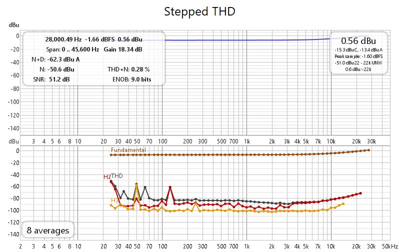
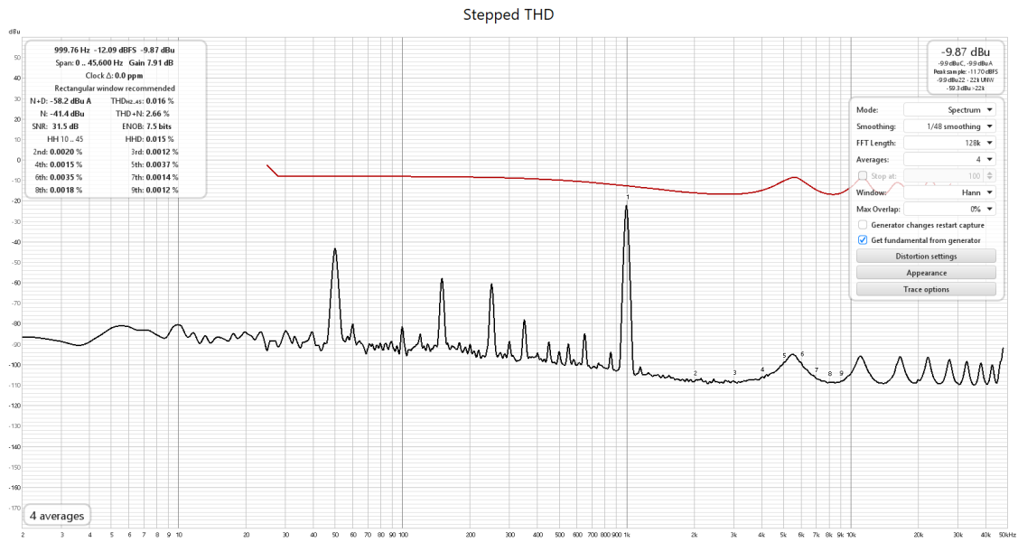
The popping and splatting sounds on the audio out appear to have gone. I've manage to run a REW sweep this morning. Usually the stepped sine FFT/Noise measurement would stop after a couple of measurements as the distortion threshold would be breached for the measurement as each "splat" occurred. But this time it managed to complete on two separate occasions.SP-8 second run with cal.png

It is not the prettiest picture in the world, and the FR does have quite a rise from about 15kHz onwards.

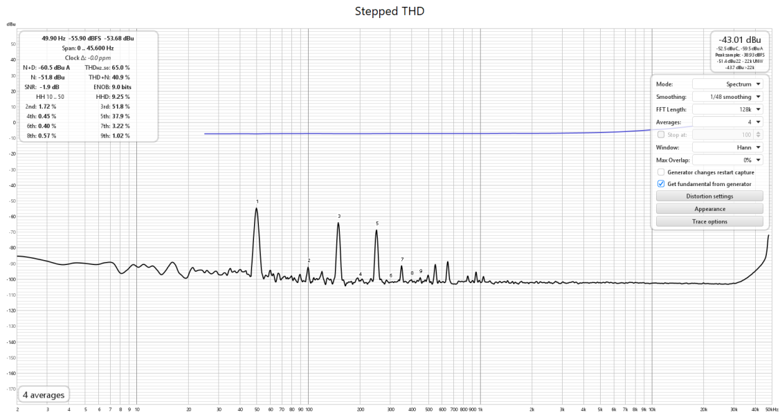
A couple of other measurements. The first is the pre-amp "at rest", turned on no signal.

SP-8 Spectrum.png

There's a chunk of hum at 50Hz with odd harmonics, quite big ones. There's a problem with the gnds somewhere, or maybe a heater supply. Through an amp the hum is clearly audible.

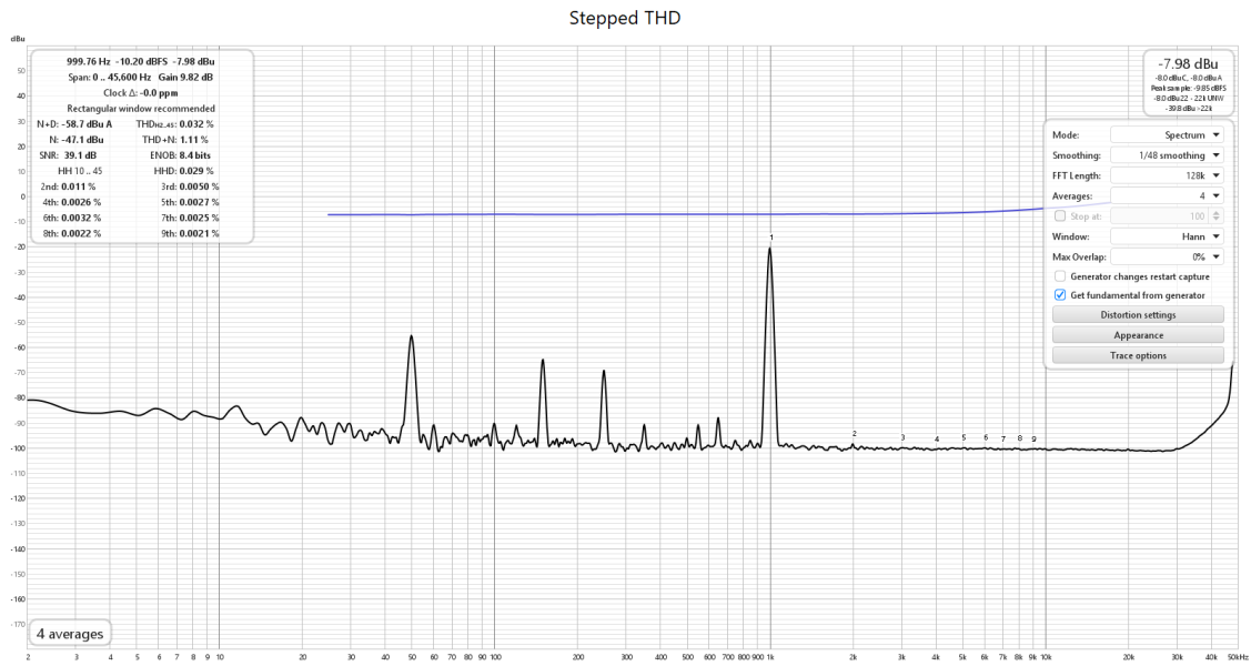
Finally a a 1Khz test tone measurement.

SP-8 1kHz tone.png

Prominent 50Hz, plus odd harmonics.

So, I've still two valve bases in the MM section to change for new ones and I will reflow the solder joints in the Line section as I reflowed the ones in the PSU section and check the grounding.

But still, I'm measuring an oscillation on the voltage after the anode/plate resistors of V4 and V5 (as before). I did notice previously that measuring V4/5 anode voltage made the audio output signal "wander" too, slow oscillation until it came to rest in unison with the anode voltages. I'm simply not going anywhere near the anodes of V4/V5 with a DVM and it results in the output audio not wandering at all.

The voltage after the zener stack into V8 is still around 335V, not the 394V on the schematic...I'm growing increasing wary of schematic voltages.

I couldn't spot any HF oscillations on the B+1, B+2 or 24V rails with my 'scope and after the swapping out of valve bases V7 and V8, I'm seeing no random crashes or spikes in the B+1 or B+2 rails.

But a little progress...

Oh, and I should add that the 555 mute circuit is working correctly. I did wonder if those little LDRs are causing interference to the audio out, but they check out just fine from what I can measure.
 
Last edited:
But still, I'm measuring an oscillation on the voltage after the anode/plate resistors of V4 and V5 (as before). I did notice previously that measuring V4/5 anode voltage made the audio output signal "wander" too, slow oscillation until it came to rest in unison with the anode voltages. I'm simply not going anywhere near the anodes of V4/V5 with a DVM and it results in the output audio not wandering at all.
The grids of V5a and b need stopping resistors. The value is likely not critical- 1K ought to work. Without them you can get weird oscillations! Grid stopping resistors are simply good design/wiring practice. They should be as close to the grid of the tube as you can get them. My surmise is you'll have to cut traces on the board and place the resistors on the bottom.

If stopping resistors are not present, the trace on the board can act as a transmission line that is improperly terminated by the grid. This results in a reflection and that can set up the oscillation. Stopping resistors, in concert with the input capacitance of the tube (Miller Effect) can be used to reduce the circuit's vulnerability to RFI.

Without that particular variable nailed down I wouldn't even bother to examine other possibilities. If its still there after this is done then you can proceed. But I think you'll find the preamp sounds better. You may find that some of the hum is gone too.
 
  • Like
Reactions: DonH50
The grids of V5a and b need stopping resistors. The value is likely not critical- 1K ought to work. Without them you can get weird oscillations! Grid stopping resistors are simply good design/wiring practice. They should be as close to the grid of the tube as you can get them. My surmise is you'll have to cut traces on the board and place the resistors on the bottom.

If stopping resistors are not present, the trace on the board can act as a transmission line that is improperly terminated by the grid. This results in a reflection and that can set up the oscillation. Stopping resistors, in concert with the input capacitance of the tube (Miller Effect) can be used to reduce the circuit's vulnerability to RFI.

Without that particular variable nailed down I wouldn't even bother to examine other possibilities. If its still there after this is done then you can proceed. But I think you'll find the preamp sounds better. You may find that some of the hum is gone too.
It is interesting that you mention that, because I wondered that too.

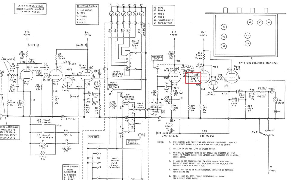
Notice that on the Mk II version on the SP-8, V5a/b have just such a resistor, marked below.

Grid resistor.png

Also, that V2, V3 and V6 all have 1K grid resistors.

I don't mind cutting tracks for the sake of stability.
 
It is interesting that you mention that, because I wondered that too.

Notice that on the Mk II version on the SP-8, V5a/b have just such a resistor, marked below.
Look at that- I even called the value! I think we can surmise this was a problem in the Mk1. You may notice the preamp is lower noise with stopping resistors installed despite the Johnson noise added by the series resistance :)
 
  • Like
Reactions: chiily
Look at that- I even called the value! I think we can surmise this was a problem in the Mk1. You may notice the preamp is lower noise with stopping resistors installed despite the Johnson noise added by the series resistance :)
Yep, you called it spot on :)

A pair of Dale RN60 resistors fitted...I shall hook it back up to test...or should I continue on to V6?
 
It is interesting that you mention that, because I wondered that too.

Notice that on the Mk II version on the SP-8, V5a/b have just such a resistor, marked below.

View attachment 145892

Also, that V2, V3 and V6 all have 1K grid resistors.

I don't mind cutting tracks for the sake of stability.
shorten one side of the connection leg of the resistor and solder it as close as possible to grid of tube.
If that doesn't help enough, you can also push a ferrite bead over the connection leg to increase the protection against oscillation of the amplifier stage
 
  • Like
Reactions: chiily
Squeezing the grid stoppers into place for V6 is going to be a challenge with the large 10uF (C10) output caps crowding the valve. In fact it is not getting the resistors in, it's more cutting the track to pins 3 and 7. I'll remove both C10s to get the resistor attached to the bottom on pin 7/2. There's much more space around the MM stage.

I've just been reading Merlin Blencowe's excellent book, "Designing High-Fidelity Tube Preamps" about grid stoppers, their purpose and the noise they can generate. With Gs being 1k the noise will be negligible. I believe that Dale RN60s are low noise too, I've used them in SS phono stages before.

Thank you again for your invaluable and excellent help.
 
SP3, SP3a, SP3a1, SP3a2, SP3b, etc... I have a modified SP3a1 and during its tenure in my system I saw several "quiet" changes to the design. My friend had a shiny new SP6, and I had a D79, that saw similar progressions. Back then I was working as a tech so was able to see the changes and make them myself. The last (third or fourth overall) time the zener string died in my SP3a1, taking out various other components, I boxed it up and haven't touched it since. I sold the D79 years ago; really wanted to keep it it, but just couldn't justify having it sitting in the box and did not have a place for it in my then (or now) current system. I think I brought it up to D79a status, but not D79b.
 
Squeezing the grid stoppers into place for V6 is going to be a challenge with the large 10uF (C10) output caps crowding the valve. In fact it is not getting the resistors in, it's more cutting the track to pins 3 and 7. I'll remove both C10s to get the resistor attached to the bottom on pin 7/2. There's much more space around the MM stage.

I've just been reading Merlin Blencowe's excellent book, "Designing High-Fidelity Tube Preamps" about grid stoppers, their purpose and the noise they can generate. With Gs being 1k the noise will be negligible. I believe that Dale RN60s are low noise too, I've used them in SS phono stages before.

Thank you again for your invaluable and excellent help.
You really don't need such large coupling caps! That preamp does not have enough grunt to drive an amp with a 10K input impedance. So why have such a large cap? Even if you were driving a 10K input impedance, the cap wouldn't need to be that large a value. ARC recommends 30K as a minimum input impedance for the amps their later preamps can drive; if you go by that metric you could use a 3.3uf cap and have the same (1.6Hz) cutoff frequency you have now. You'd have the added advantage of a the simple fact that a 3.3uf cap will sound better than a 10uf cap too.
 
Another day, and another learning experienceSP- grid resistors in place V5-V6.png

...and what looks like a step backwards.

I've installed grid stoppers (1K) on both sides of V5 and V6. At that appears to have triggered some oscillation, well I think it is that, though certainly a change to the output spectra.

Hmm, I will try bypassing the ones on V6 with a bit of wire...
 
You really don't need such large coupling caps! That preamp does not have enough grunt to drive an amp with a 10K input impedance. So why have such a large cap? Even if you were driving a 10K input impedance, the cap wouldn't need to be that large a value. ARC recommends 30K as a minimum input impedance for the amps their later preamps can drive; if you go by that metric you could use a 3.3uf cap and have the same (1.6Hz) cutoff frequency you have now. You'd have the added advantage of a the simple fact that a 3.3uf cap will sound better than a 10uf cap too.
I agree they are too big. Maybe an up date in a bit but I don't want to change the amp too much at this stage. Just get it working reliably and consistently.
 
Don't forget that grid stoppers need to be pure resistive, thus any film types trimmed in spirals is contraproductive and might even provoke instability!
Old type carbon composit is what is needed !
Test with these resistors you will see what happend.
 
  • Like
Reactions: chiily
Well, I finally have it playing some music through the Line stage, even with that strange spectra. I'm not sitting down to listen atm, just on in my office gauging its boogie factor. And it is sounding pretty good so far, a little loose in the bass, not so clear as either my miniDSP Flex or my DIY valve pre, though not bad at all. It had a bit of a bass burble for about 30 secs into both channels after five minutes of playing (could have been my PC, I'm running through USB into a Focusrite Solo 3rd Gen). Just happened again!! It's been running about 30 minutes now with no nasties to report, other than lots of CPU audio hash from my PC.

Amazing how loud a little Leak ST20 will go, even with reasonable insensitive speakers.PXL_20250218_094955680.jpg

If I find a bit of time this afternoon I'll install grid resistors in the MM stage. Bypass the ones on V5 to try to understand why the spectra ia what it is now. Probably do the by pass first.
 

About us

  • What’s Best Forum is THE forum for high end audio, product reviews, advice and sharing experiences on the best of everything else. This is THE place where audiophiles and audio companies discuss vintage, contemporary and new audio products, music servers, music streamers, computer audio, digital-to-analog converters, turntables, phono stages, cartridges, reel-to-reel tape machines, speakers, headphones and tube and solid-state amplification. Founded in 2010 What’s Best Forum invites intelligent and courteous people of all interests and backgrounds to describe and discuss the best of everything. From beginners to life-long hobbyists to industry professionals, we enjoy learning about new things and meeting new people, and participating in spirited debates.

Quick Navigation

User Menu

Steve Williams
Site Founder | Site Owner | Administrator
Ron Resnick
Site Owner | Administrator
Julian (The Fixer)
Website Build | Marketing Managersing