ARC SP-6A Tube Preamp

I haven't looked for a while since getting out of the design side of things and retiring. Wirewound resistors actually have the lowest noise, but have so many other issues (inductance and high tempco among them) that they are rarely used IME. Even for power applications thick-film metal resistors have pretty much taken over, likely driven by the proliferation of SMPS that require good high-frequency performance (high self-resonance frequency).
The best for speaker xover and normal tube voltage isabellenhütte phb resistors..i have tested a lot of resistors. Expensive but the sound is impressive every day.
Exsample

For high voltage tubes nicrom switzerland
 
The best for speaker xover and normal tube voltage isabellenhütte phb resistors..i have tested a lot of resistors. Expensive but the sound is impressive every day.
Exsample

For high voltage tubes nicrom switzerland
Those Digikey Resistors are pricey....:)

I'll stick with the Dales for the moment. I'm not seeing any persistent oscillations on the audio output.

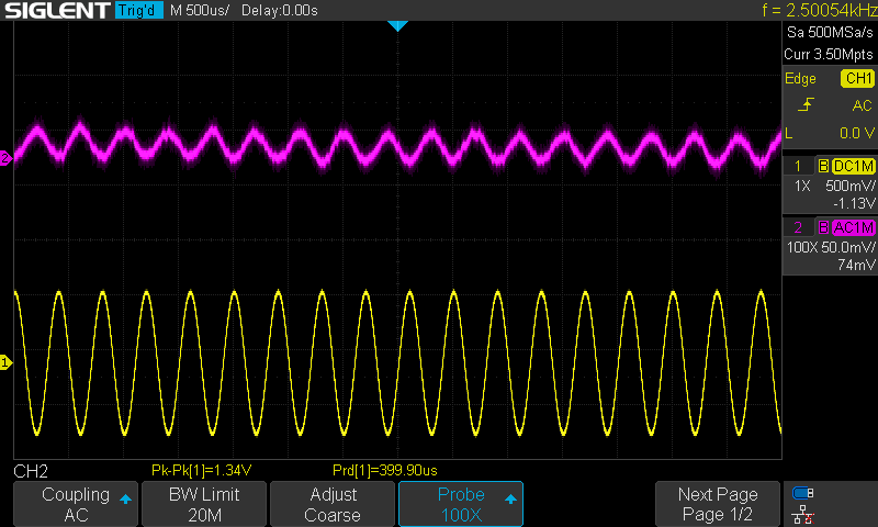
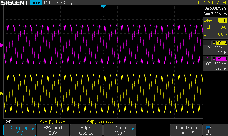
Couple of pictures from the 'scope.

Purple on a 100x probe, Yellow on a 1x probe.

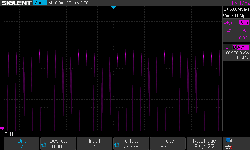
Purple B+1 HT. The "noise" is about 1 division, 5mV.


SDS00013.png

Purple Anode of V4, Yellow Audio out.

SDS00018.png

Purple, anode of V5, yellow audio out.

SDS00022.png


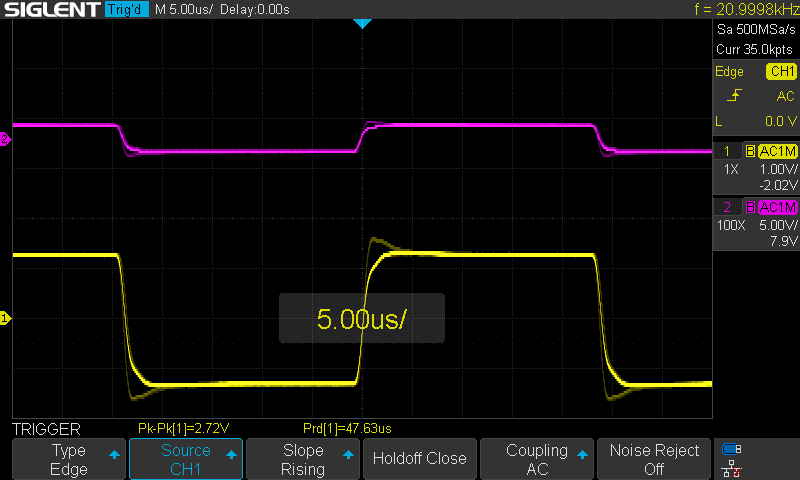
Square wave time...

20kHz, purple anode voltage on V5, Yellow audio out.

A strange blip on the leading and trailing edges of the anode voltage and audio out.

SDS00034.png

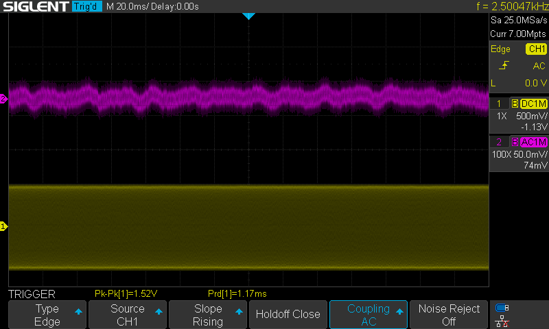
I also spotted this strange "burp"

From this...

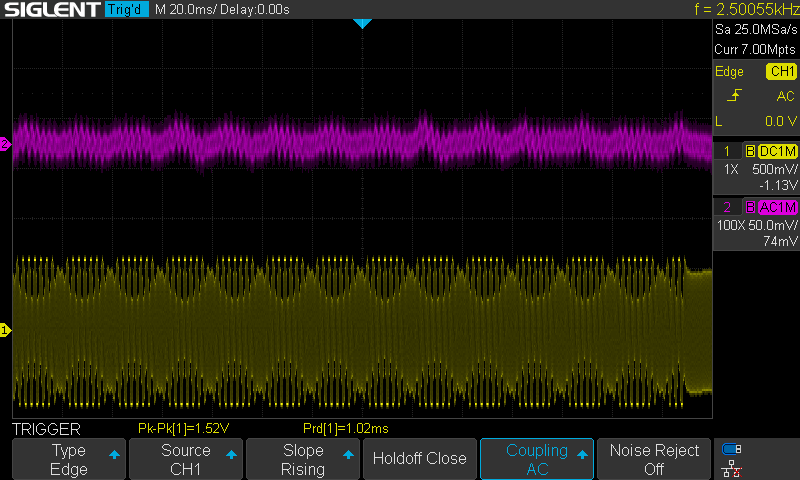
Purple anode voltage of V4, yellow audio output.
SDS00015.png

To this...

SDS00014.png

Is this a burst of oscillation? I haven't been able to correlate this burst with one of the audio "burp and crackles" I hear in the speakers.

The anode voltage, is not wandering over +/-6V as it would previously, just within one div during normal operation. Also, I'm not seeing the HT rails crashing randomly anymore, as the amp did when I started....just this burst of interference/oscillation in the picture above.
 
Last edited:
  • Like
Reactions: DasguteOhr
In fact, as far as I remember, Caddok is one the few existing independent companies supplying ultra low noise precision resistors for instrumentation. Vishay slowly acquired most of the competition along the years - last time I checked the best I could find were Vishay Z-Foil Resistors and VHP Series Vishay Foil (not searching for audio purposes, BTW). I heard about low noise precision wirewound resistors but I have never seen them.
Caddock was acquired by Vishay about 10 years ago but wisely has seen fit to not mess with them. Mills makes a non-inductive wirewound resistor.
Those Digikey Resistors are pricey....:)

I'll stick with the Dales for the moment. I'm not seeing any persistent oscillations on the audio output.

Couple of pictures from the 'scope.

Purple on a 100x probe, Yellow on a 1x probe.

Purple B+1 HT. The "noise" is about 1 division, 5mV.


View attachment 146028

Purple Anode of V4, Yellow Audio out.

View attachment 146027

Purple, anode of V5, yellow audio out.

View attachment 146026


Square wave time...

20kHz, purple anode voltage on V5, Yellow audio out.

A strange blip on the leading and trailing edges of the anode voltage and audio out.

View attachment 146030

I also spotted this strange "burp"

From this...

Purple anode voltage of V4, yellow audio output.
View attachment 146032

To this...

View attachment 146031

Is this a burst of oscillation? I haven't been able to correlate this burst with one of the audio "burp and crackles" I hear in the speakers.

The anode voltage, is not wandering over +/-6V as it would previously, just within one div during normal operation. Also, I'm not seeing the HT rails crashing randomly anymore, as the amp did when I started....just this burst of interference/oscillation in the picture above.
If the purple is the B+ that supplies the tube (so not the actual plate Voltage) then you have a noise problem- its as if the power supply isn't well bypassed. There's a 2uf cap in the power supply bypassing a 200uf cap (both after the active regulation) for the 402V output. Were they changed out?
 
  • Like
Reactions: microstrip
If the purple is the B+ that supplies the tube (so not the actual plate Voltage) then you have a noise problem- its as if the power supply isn't well bypassed. There's a 2uf cap in the power supply bypassing a 200uf cap (both after the active regulation) for the 402V output. Were they changed out?
The purple is at V4 and V5's pin 1. Pin 6 was the same. That is after the Ra 301k.

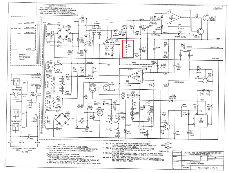
Are you referring to C17, the 200uf here...

PSU C17 marked.png
Is it deleted in my version of the SP-8 rev 3, see note ##. C19 was a 0.22uF bypass cap.

I have not replaced C18, though I do have a replacement handy, at 2uF.

R68, (there are two in the schematic!), the 1R, 2w one measures 1.5R. when measuring I've never seen any voltage at the C18/R68 junction. I do have a replacement handy for R68.

I didn't get a chance today to try a 47uF across B+1, nor to fit the PSU grid stopper resistors (I've some CC for them, especially the grid stoppers for the 12BH7A), too cold in the shed! :)

Thank you again for your help and invaluable insight.
 
Last edited:
The purple is at V4 and V5's pin 1. Pin 6 was the same. That is after the Ra 301k.

Are you referring to C17, the 200uf here...


Is it deleted in my version of the SP-8 rev 3, see note ##.

I have not replaced C18, though I do have a replacement handy, at 2uF.

R68, (there are two in the schematic!), the 1R, 2w one measures 1.5R. when measuring I've never seen any voltage at the C18/R68 junction. I do have a replacement handy for R68.

I didn't get a chance today to try a 47uF across B+1, too cold in the shed! :)
200uf for C17 seems like a lot for a 12BH7 to handle! But there should be some capacitance there else the supply could be unstable. I would try 22uf and see how things look. No telling why ARC deleted that part but it is possible they didn't try a lot of different values. Even if you had a semiconductor power supply 200uf would be a lot to handle!

The way the power supply should work is the regulator has an output impedance that is a function of its bandwidth. At some frequency it runs out of bandwidth so the output impedance increases. At that point the capacitor value takes over so to keep the output impedance as flat as possible across the audio band. So its very likely the 200uf value was way too high!

I really doubt only 2uf is enough...
 
  • Like
Reactions: chiily
I did manage to pop out and brave the shed. I feel that we are inching closer...

Where C17 should have been installed I grabbed the only 450V cap I had, which is 47uF and popped it in. Note that the position of C17/47uF is way back in the PSU section and not near the valves.

This is in the noise on the anode of V5. No signal applied, muted output.

Where purple is the voltage at V5 anode, with a 100x probe, one div is 0.5mV.

SDS00050.png

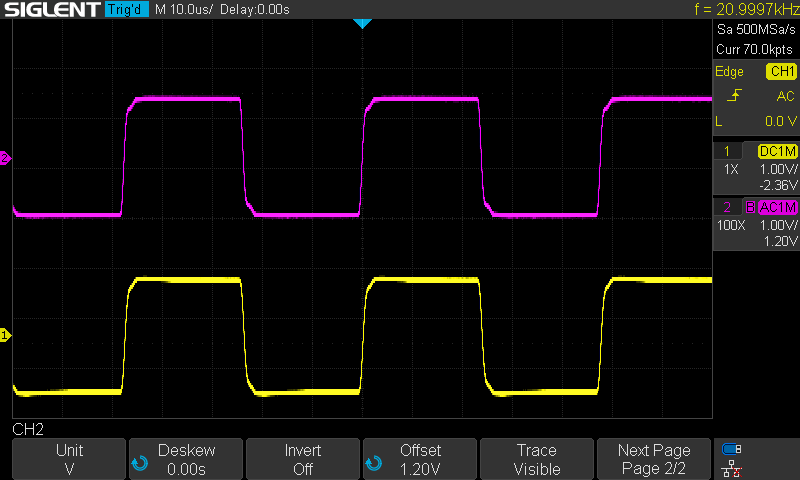
Next up is a square wave @ 21kHz, 1.4V input.
Purple trace in the anode of V5 and the yellow the output of the same audio channel that corresponds to the V5 anode pin being measured.

SDS00051.png

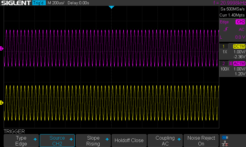
And finally a simple sine wave at 21kHz, 1.4V input. Probe positions as the previous plot.

SDS00055.png

And finally a capture of the very small, tiny, modulation on the anode voltage. This is at 50mV/division on a 100x probe. Previous with the scope set to 1V/div one could see this ripple modulating the anode (and output) voltage. The addition cap in C17, seems to have taken that out.

SDS00056.png


I don't have time to listen to the pre-amp tonight, cold enough that typing is tricky. That is the acid test when those little "burps" and "splats" can be easily heard. Encouragingly though that I've not seen a repeat of this in the last hour on the 'scope. :)

SDS00016.png

Little steps....
 
Where C17 should have been installed I grabbed the only 450V cap I had, which is 47uF and popped it in. Note that the position of C17/47uF is way back in the PSU section and not near the valves.
That seems to be an improvement! I'd hang with that for a while and see what you think over time. I suspect though that 47uf is still a little high, but its a whole lot better than 200uf!!

I noticed the line stage has local film B+ bypass caps that must be right by the tubes. That's a good move since noise can occur on the traces between the power supply and where that power is being used. I don't seem them in the phono section though! Odd.

How are your power supply Voltages? Inching towards spec?
 
How are your power supply Voltages? Inching towards spec?
Last time I looked the anode voltages were about 10V higher than the schematic and stable, though still prone to wandering on first measuring them. But as you can see above on the fourth 'scope capture there is the slightest ripple on the anodes. :)

The voltage at the top of the Zener stack, well, it was just doing it's own thing at about 335v...I just ignore it TBF :)

I have on order, pickup tomorrow, a few 10uF, 450V caps, so I can do a bit of mix and match, maybe move the 10uFs right on the top of the Ras.

Though space is tight, I will fit CC, 1k grid stoppers to V7 and V8.

Let's hope the listening session goes well tomorrow.

One thing I am finding, and it is as a result of the fabulous help you have all provided, is that I have learnt so much about valves and valve operation, so much so that I fancy trying to could up with a simple preamp... obviously, not with a complex PSU like this SP-8 has, what were ARC thinking. :)

I also own you a few measurements of the heater voltages/signals and measurements of the earth/gnding. I'll get there :)
 
Last edited:
  • Like
Reactions: Atmasphere
Hm. It should be slightly above the output Voltage by about 4 - 7 Volts. Is it connected to the grid of the 12BH7? When did you last look at the Zener Voltage?
I did check a couple of days ago.

When I was testing the PSU by applying resistors across the B+1 and the B+2 the voltage at the top of the Zener stack (Vz) would rise as the resistance of the resistors was lowered. For example with two 33k resistors, one across each rail Vz rose to about 360v and with 24k across each rail Vz rose to close to the 390v as indicated by the schematic. In both instances the regulated voltages, B+1 and B+2, remained the same. Note that no valves were installed.

Removing the ECC83, V8, did push Vz to 394V. I did this before adding the resistors.

I did take the time to double check the zeners in the stack and they all checked out as diodes :) and of the same type.

Vz has always been incorrect, other than when loading the HT rails with resistors. Also, that the V8's grid voltage from U2 should be 6V, but on mine it measures around 7V, whilst both inputs to U2 are 6.9V. The resistances of the resistor divider stack, R51, R52 and R68 (the other R68!) are all correct. I had considered decreasing R68 (12.1k) to push the output U2 towards 6V, if I understand that U2 is a comparator between a ref voltage (LM329) and the B+1 voltage. Though I always thought comparator's output just swung rail to rail (well nearly) if there was a voltage imbalance at their inputs.

PSU Measured voltages.png
 
Last edited:
if I understand that U2 is a comparator between a ref voltage (LM329) and the B+1 voltage. Though I always thought comparator's output just swung rail to rail (well nearly) if there was a voltage imbalance at their inputs.
U2 is a feedback loop controlling the 12AX7. The feedback coming in on the non-inverting input since the output phase is inverted by the 12AX7. C34 allows higher frequencies to bypass the resistors. But it looks like its being used also to trim the 402V output slightly.

If they are using that to trim the B+ one of the fixed resistors could be made adjustable (see Note 6). It stands to reason that changing the 12AX7 will also affect the output Voltage due to this feedback loop although the output Voltage is supposed to derive from the Zener stack according to the Note. The transconductance of the tube itself is inside the loop so I think they didn't have a 100% grasp of how to do this.

If the 12BH7 is to the pass regulator, its easy enough to use an opamp to servo control it directly using a Zener stack as a Voltage reference. That is how we did the high Voltage regulation in our early MP-1 preamps, although we used a 6080 for the pass regulator.
 
  • Like
Reactions: chiily
So I could replace R68 with say a 20k multi turn pot, using just one leg and the wiper. Set it to 12k and tweak the resistance up and down to drive U2?

Power dissipation in the 12.1k is very small as it is.

Edit: Actually this is madness, the voltage out of U2 would swing wildly with a small change in R68. best to do a little calculation and replace R68 with a slightly higher value.

Though I may have a 357k I could substitute for R51.
 
Last edited:
I thought this morning we would start off with a little music to compensate for the head scratching over this SP-8.

I've not made any other changes, installation the grid stoppers for the PSU (V7/V8 and V2/V3 come to that!) and any tweaking to R68 (12.1k)/R51/R52 have taken a back seat for the moment whilst I figure out if we have made progress, with some music...

Well, it appears we have!!

One hour of listening and only one very small "splat", and I mean small. None of the crackle, rustle, burr, etc that I was hearing before. I did managed to spot the 'scope trace as the "splat" occured, and the anode voltage on V5 suddenly dropped with the "splat".

Thank you (@Atmasphere ) for your post post on the workings of U2 and the influence of V8. I'm going to attach the 'scope to the grid of V8, output of U2, to see if I can trace something here.
 
I'm kinda enjoying this now....

Fitted grid stoppers to V8, 1.2k 0.5W carbon comps and the top of the zener stack rose to 385V; same valves. Fitting the grid stoppers was relatively straight forward for V8 as the grid trace is underneath the board. The B+1 is still not hitting 402V, resting at 396V atm.

I still need to fit grid stoppers to V7, but I'll have to take the valve base out to to that as there is a link between pins 2 and 7 on top of the board, under the valve base.
 
Last edited:
  • Like
Reactions: DasguteOhr
When the preamp works correct you can test it.
You can put a 7044 tube in as 12bh7a this a bit stronger deliever more current( 20mA each triode system). You need a socket adapter 7044 to 12au7/12bha7 ( diffrent pinout)google it.
 
  • Like
Reactions: chiily
Though I may have a 357k I could substitute for R51.
R51 is the one to adjust. If you had selected a resistor that was on the low side of 330K and put a 10K reostat in series, you could do the adjustment.

Its good to hear all your work has resulting in good progress!

Its telling that the stopping resistors had a desirable effect on the regulator. I would finish that up before trying to do any adjustable bit with R51. You are within 6V, which would be considered 'good enough for government work' as they say ;) I suspect the 402V shown is a nominal Voltage and may not reflect how all examples of this preamp actually behaved.
 
  • Like
Reactions: chiily
Thank you for your encouragement :). I've learnt so much troubleshooting valves amps over the past few weeks. So, thank you all.

Great idea about adding a 10k pot in series with R51, I shall try that.

I bit the bullet and added two grid stoppers to V7. Removed the valve base and cut four tracks to isolate pins 2 and 7. I had to add a couple of wires underneath to take the top of the Zener stack to V8, pins 1 and 6. Tripled checked all my work (just realised that I didn't add back the back to back ZD and diode, tomorrow's job).

No change to the voltages nor their behaviour. Top of the Zener stack is 385V, B+1 is 396V and B+2 394. So all good so far.

Too cold in the shed to do much more tonight and I'm out at the Bristol HiFi show tomorrow. I'll have to wait until the weekend for some music.
 
  • Like
Reactions: Atmasphere

About us

  • What’s Best Forum is THE forum for high end audio, product reviews, advice and sharing experiences on the best of everything else. This is THE place where audiophiles and audio companies discuss vintage, contemporary and new audio products, music servers, music streamers, computer audio, digital-to-analog converters, turntables, phono stages, cartridges, reel-to-reel tape machines, speakers, headphones and tube and solid-state amplification. Founded in 2010 What’s Best Forum invites intelligent and courteous people of all interests and backgrounds to describe and discuss the best of everything. From beginners to life-long hobbyists to industry professionals, we enjoy learning about new things and meeting new people, and participating in spirited debates.

Quick Navigation

User Menu

Steve Williams
Site Founder | Site Owner | Administrator
Ron Resnick
Site Owner | Administrator
Julian (The Fixer)
Website Build | Marketing Managersing