Thanks to Folsom for explaining AC wiring, phase, and polarity in such detail, to correct and/or clarify what was previously posted! Excellent job!

Electrical phase...
- Thread starter Stereophonic
- Start date
You are using an out of date browser. It may not display this or other websites correctly.
You should upgrade or use an alternative browser.
You should upgrade or use an alternative browser.
Empirical Audio
Industry Expert
Electrical AC connections to components can vary, even if the electrical IEC is wired the same. This is because of the way the secondary of the transformer in the component is wired. There is always a "dot" side to the input winding and a "dot" side to the output winding. In countries that use one phase, if the AC neutral is connected to the dot side of the primary, the dot on the secondary side can be connected to either side of the bridge rectifier. This means that in theory, it does not matter which side of the primary gets the N or neutral and which side gets the L or hot. The reality is that transformers are not perfect though, and the leakage across a transformer can be different for one side of the winding and the other. This means that the capacitance across both sides of the windings from primary to secondary is different.
The Neutral is connected to earth ground at the panel and the DC common on the secondary of the transformer after the bridge rectifier is also connected to earth ground. This provides more low-impedance paths for current to flow, particularly if the circuit is not correctly designed. The electrical "distance" from either side of the secondary to the earth ground is one diode drop, but the model shows that from the secondary to the primary is two different capacitances. This I think is the primary difference between connecting the primary either way. Otherwise, it is symmetrical. At 0Hz, the primary and secondary are essentially low impedance resistors, so the path through these capacitances to earth ground is different depending on how the primary is connected.
This is my back of the envelope analysis.
BTW, it is probably not accurate to call this "phase". More like AC polarity. There are typically 2 phases in any US AC panel. The circuits for all of the interconnected audio components should use only one of those phases, unless you like the sound of 60Hz hum.
Steve N.
Electrical AC connections to components can vary, even if the electrical IEC is wired the same. This is because of the way the secondary of the transformer in the component is wired. There is always a "dot" side to the input winding and a "dot" side to the output winding. In countries that use one phase, if the AC neutral is connected to the dot side of the primary, the dot on the secondary side can be connected to either side of the bridge rectifier. This means that in theory, it does not matter which side of the primary gets the N or neutral and which side gets the L or hot. The reality is that transformers are not perfect though, and the leakage across a transformer can be different for one side of the winding and the other. This means that the capacitance across both sides of the windings from primary to secondary is different.
The Neutral is connected to earth ground at the panel and the DC common on the secondary of the transformer after the bridge rectifier is also connected to earth ground. This provides more low-impedance paths for current to flow, particularly if the circuit is not correctly designed. The electrical "distance" from either side of the secondary to the earth ground is one diode drop, but the model shows that from the secondary to the primary is two different capacitances. This I think is the primary difference between connecting the primary either way. Otherwise, it is symmetrical. At 0Hz, the primary and secondary are essentially low impedance resistors, so the path through these capacitances to earth ground is different depending on how the primary is connected.
This is my back of the envelope analysis.
BTW, it is probably not accurate to call this "phase". More like AC polarity. There are typically 2 phases in any US AC panel. The circuits for all of the interconnected audio components should use only one of those phases, unless you like the sound of 60Hz hum.
Steve N.
Steve, while transformers may not be perfect due to inner and outer winding being part of the inherit nature to fit the amount of turns onto the core, the reason to swap L & N at the transformer is because of capacitance to the enclosure. It isn't the capacitance to the secondary that is the concern. You can still have parasitic capacitance to the enclosure (SG) even when you have a low leakage transformer that deploys a static shield between windings. It is the winding that is on the outside that does it, so obviously the desire is not to have it be Line since the outer winding is the closest to another path (SG). The power use (current flow & voltage drop) occurs in the device, so the potential of Neutral is lower and therefor more desirable to be closest to the enclosure (SG) since Neutral to SG doesn't flow - as it makes no path through transformer windings.
Contrary to somewhat popular belief, leakage itself is not a negative between primary and secondary. Generally speaking it's a good thing in audio because what is "leaking" is primarily higher frequency, higher order, noise. In fact for this reason dual bobbin and other non-toroidal transformers are popular in high in equipment because of this feature. (static shields in a toroidal help them perform well, too) But the capacitance between the outside of the transformer and enclosure tends to add noise because there is a path with strong potential to "siphon electrons from" if it's Line.
"Neutral" or PG on the secondary side of a transformer exists literally in a center tap transformer, and virtually with a dual secondary transformer. It is not necessarily connected to SG at all. In fact if the isolation is high enough you can have electronics meet all UL/CE without any SG connection at all (to the enclosure, a 2 wire cord to it). I personally don't like them connected because it opens a can of worms with parasitics & such. It can be done well, but I haven't found it to be desirable - or necessary to meet any specs etc. For balanced (signal) gear it's not a good idea. I find localized capacitors between PG and SG works well. (this can all get really confusing now is we use SG as a term for signal ground, which I am not in this thread, but it is more correct that SE, safety earth.... grounding terminology is a basket case)
Pole is a great word, it is a noun, and the root word for polarity.
Last edited:
Wow. I had no idea you sometimes had 3 phase... But it is different from place to place...I'm not going to complain about having the same socket style everywhere in North America... I'll leave that mess you you guys over there.
But I do have to wonder if you have 1 phase split into 3 poles? It is possible... True 3 phase is weird. This is what it looks like.
View attachment 39493
Yes, it is exactly what we have - true 3 phase - a blue (neutral) and three different phases (hot). If you connect to two hot you get 398 Vac! But is is great to drive three phase motors, for example in lifts or pool motor filters. In large spaces we can connected sets of fluorescent lamps to different phases to reduce flicker.
Empirical Audio
Industry Expert
Steve, while transformers may not be perfect due to inner and outer winding being part of the inherit nature to fit the amount of turns onto the core, the reason to swap L & N at the transformer is because of capacitance to the enclosure. It isn't the capacitance to the secondary that is the concern. You can still have parasitic capacitance to the enclosure (SG) even when you have a low leakage transformer that deploys a static shield between windings. It is the winding that is on the outside that does it, so obviously the desire is not to have it be Line since the outer winding is the closest to another path (SG). The power use (current flow & voltage drop) occurs in the device, so the potential of Neutral is lower and therefor more desirable to be closest to the enclosure (SG) since Neutral to SG doesn't flow - as it makes no path through transformer windings.
Contrary to somewhat popular belief, leakage itself is not a negative between primary and secondary. Generally speaking it's a good thing in audio because what is "leaking" is primarily higher frequency, higher order, noise. In fact for this reason dual bobbin and other non-toroidal transformers are popular in high in equipment because of this feature. (static shields in a toroidal help them perform well, too) But the capacitance between the outside of the transformer and enclosure tends to add noise because there is a path with strong potential to "siphon electrons from" if it's Line.
"Neutral" or PG on the secondary side of a transformer exists literally in a center tap transformer, and virtually with a dual secondary transformer. It is not necessarily connected to SG at all. In fact if the isolation is high enough you can have electronics meet all UL/CE without any SG connection at all (to the enclosure, a 2 wire cord to it). I personally don't like them connected because it opens a can of worms with parasitics & such. It can be done well, but I haven't found it to be desirable - or necessary to meet any specs etc. For balanced (signal) gear it's not a good idea. I find localized capacitors between PG and SG works well. (this can all get really confusing now is we use SG as a term for signal ground, which I am not in this thread, but it is more correct that SE, safety earth.... grounding terminology is a basket case)
Pole is a great word, it is a noun, and the root word for polarity.
So, it would follow that transformers that are bobbin-wound could have the same capacitance to the chassis from either L or N?
So, it's basically a crap-shoot for toroidals. They don't publish which side of the winding ends-up on the outside. If you pick the wrong side, then the capacitance from the outer winding to the chassis is high. I guess you need to put it in a system and them switch the connections to find the best SQ?
Steve N.
Empirical Audio
Yes it can.
I don't think anyone publishes. I have multiple Hammond transformers with phase dots, but there isn't a consistency.
You can hear the difference. Try it... It can be a funny experience. You can play with flipping your preamp and amp. You'll likely find one direction sound best. That's the subjective test. The cheater plug test works that was posted earlier in the thread to get the correct one.
Stereophonic: The plug style doesn't matter, in your country the transformer simple puts out a different voltage. You still have L, N, and SG. But I don't know if you have 2 poles per residence from a single phase. I'm sure you're on single phase, but couldn't speak for whether you have 1 or 2 poles. It may be different from country to country, but 1 pole looks to be a common thing in some other countries besides US.
Thank you very much Folsom for your explanation and dedicated time...
As you can see, in my case the plug style matters....

Furutech outlet with hot and neutral line marked

Last edited:
Thank you very much Folsom for your explanation and dedicated time...
As you can see, in my case the plug style matters....
View attachment 39502
Furutech outlet with hot and neutral line marked
View attachment 39503
Your schematic shows an asymmetrical US power plug - German style Shucko power plugs do not identify L and N, maintaining ambiguity, although we can use the french ground hole to orientate them.
Although there is no rule to orient sockets, here many electricians will connect hot to the left (the Czech recommendation).
Thanks to Folsom for explaining AC wiring, phase, and polarity in such detail, to correct and/or clarify what was previously posted! Excellent job!
x2 !
In Australia we have a mixture of single phase and three phase power in homes, but thanks Folsom for your comprehensive explanation, we run 240 Volts ...

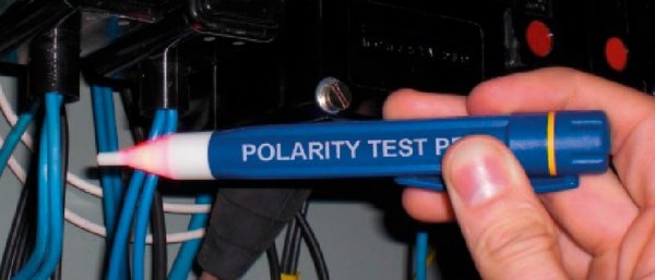
I have this one. But you can only test the hot and neutral outlet/IEC PC pin...
The question is how to verify that the, for example, amplifier internal phase is right or inverted.

The question is how to verify that the, for example, amplifier internal phase is right or inverted.
I have this one. But you can only test the hot and neutral outlet/IEC PC pin...
The question is how to verify that the, for example, amplifier internal phase is right or inverted.
View attachment 39534
The proximity polarity checker allows this check. It as is built using a sensor that is sensitive to the electric field, not current. Just checked a DVD player that does not have a grounded plug - in one position it lights a 8t cm distance and in the reverse orientation of the plug it lights at 2 cm - this is the proper position corresponding to a lower leakage current through ground. Remember that in order to break the ground line you have to use a cheater adapter to carry this measurement - you can get it from a cheap travel plug adapter set.
The "phaser" (funny name, silly) just tells you the same thing as those testers for hot wires... It does what it says on the top, it detects polarity. If you know which wire is Hot (Line) you know the polarity. The whole point of the phaser is just to make sure everything is wired with the same polarity, but clearly you can use the little hand-held versions.
If you want to know about the amplifier ask the manufacturer first. Maybe you've played with a DAC that has a phase button? Rarely does it do anything. Albums can be in or out of ultimate phase. My suggestion is not to worry about it. Polarity is a worthy concern, however, as stated previously.
If you want to know about the amplifier ask the manufacturer first. Maybe you've played with a DAC that has a phase button? Rarely does it do anything. Albums can be in or out of ultimate phase. My suggestion is not to worry about it. Polarity is a worthy concern, however, as stated previously.
The proximity polarity checker allows this check. It as is built using a sensor that is sensitive to the electric field, not current. Just checked a DVD player that does not have a grounded plug - in one position it lights a 8t cm distance and in the reverse orientation of the plug it lights at 2 cm - this is the proper position corresponding to a lower leakage current through ground. Remember that in order to break the ground line you have to use a cheater adapter to carry this measurement - you can get it from a cheap travel plug adapter set.
That isn't phase though, it is polarity still. Anyway, that is a great little trick.
Hi everybody.
Yesterday i recieved this item:

That is the operating instructions:

My objective was to detect the internal polarity of each electronic/electric device.
This item really works !!! I have confirmed that all my audio system is right connected.
As my mono amplifiers has hum sound since day one i began to test all the rest of the electric devices of my home.
I discovered refrigerator and coffee machine were connected out of phase.
Once everything tested and rightly connected amplifiers hum sound has gone.
Now i haven’t any ground loop.
Highly recommended !!!!
Yesterday i recieved this item:
That is the operating instructions:
My objective was to detect the internal polarity of each electronic/electric device.
This item really works !!! I have confirmed that all my audio system is right connected.
As my mono amplifiers has hum sound since day one i began to test all the rest of the electric devices of my home.
I discovered refrigerator and coffee machine were connected out of phase.
Once everything tested and rightly connected amplifiers hum sound has gone.
Now i haven’t any ground loop.
Highly recommended !!!!
Last edited:
I’m sorry but i can’t write any objective audio improvement.
My new router LPS is still on broken progress.

Regards !!!
My new router LPS is still on broken progress.
Regards !!!
Similar threads
- Replies
- 63
- Views
- 4K
- Replies
- 42
- Views
- 2K
- Replies
- 0
- Views
- 470
- Replies
- 7
- Views
- 2K
- Replies
- 17
- Views
- 2K
| Steve Williams Site Founder | Site Owner | Administrator | Ron Resnick Site Owner | Administrator | Julian (The Fixer) Website Build | Marketing Managersing |