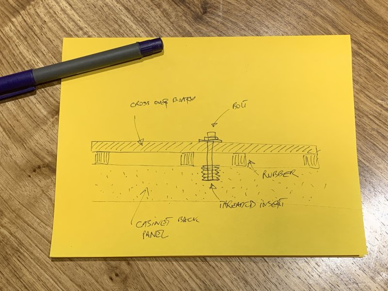
Let me try to sum up based on your various questions, and try to make things as clear as possible.
Also I have to remind you, that this is not an easy speaker to work on because of the many drivers and tight space inside the cabinets. This project is one of those: If you have to ask, then maybe consider twice before you attempt doing it yourself. I will do what I can to help, but you also have to be able to work out stuff as you go along, where to drill holes, how big they must be, how long bolts are needed, how to seal around cables with hot glue etc etc.
But on the other hand, if you have resonable mechanical skills, can work with delicate items without breaking them, then you should be able to do it. Just take your time, and think steps through before rushing and making mistakes. I’m sure a lot will make more sense, once you have all the drivers and the passive radiators out and can actually see what’s going on inside the cabinet.
Taking a step back, the point from my side was to upgrade these without making changes to the exterior of the speakers, and to only make minimal changes on the interior. If you also change the binding posts, the only difference you will see on the outside after the upgrade is the new binding posts.
Let me detail a bit more, the changes you must make on the inside to make room for the much bigger cross over, and the much thicker cables.
Stripping.
Remove the original cross overs + wiring. You also have to remove the damping material inside the midwoofer chambers, and the grey foam in the woofer chamber. The grey foam is glued in place, so remove it carefully without damaging it, as it has to be reinstalled later.
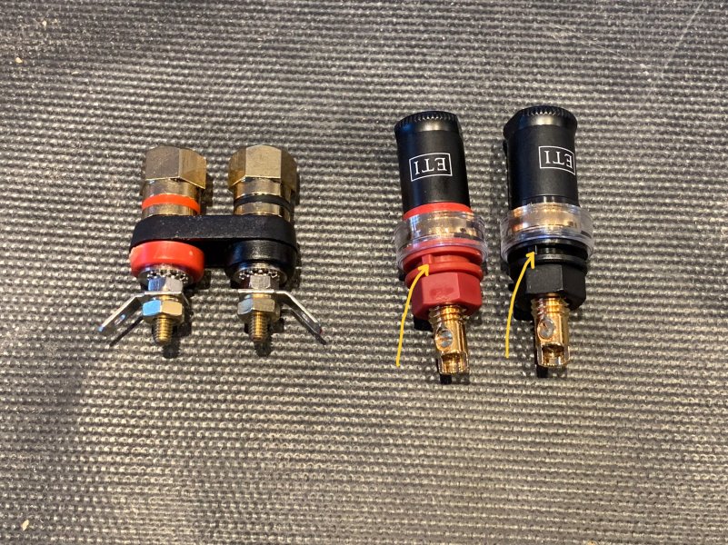
Binding posts:
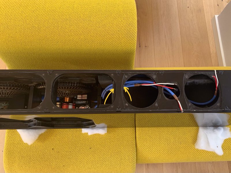
The ETI has this lille ‘’notch’’ (see yellow arrows) to prevent them spinning. You must drill/file for that. And when installing them seal with some sort of glue to make the connection air tight. I used epoxy.
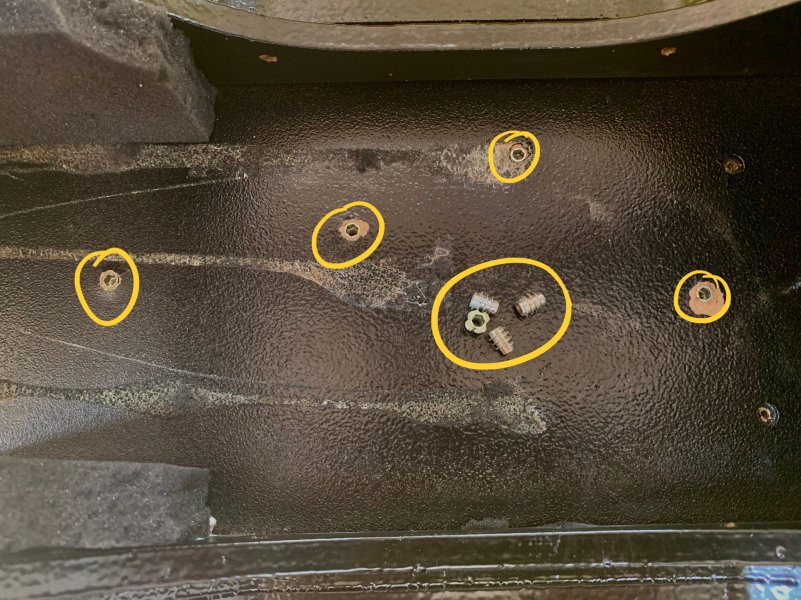
Threaded inserts:
Drill holes into the back panel to install them. DON’T drill deeper than necessary for them to sit flush as shown in the picture. Before that of course you must identify where to locate them in the back panel. When you get the cross overs, install them ‘’loosely’’ in the cabinet. Then use a nail/hammer through the mounting holes in the cross over board to mark positions. Remove cross over boards and drill for the threaded interts at the marks.
Remove small bracing:
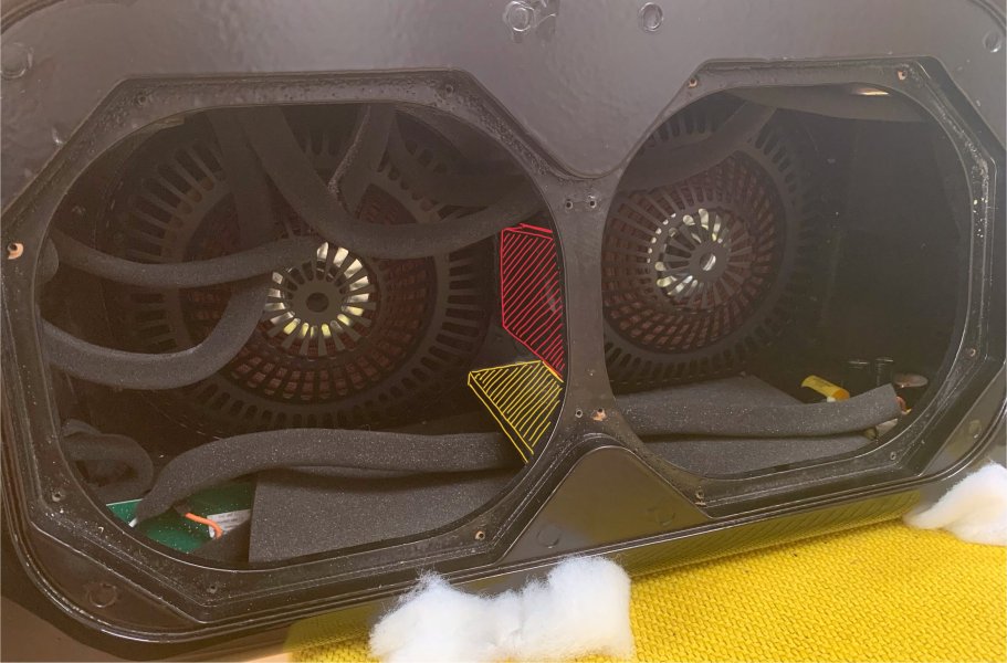
With the new cross over board being a lot bigger you need to remove a small piece of bracing towards the back of the cabinet. I have attached a picture showing this. See my yellow and red mark-up’s. The red on stays, only remove the one markd with yellow. When that is removed, the cross over board slides under the red one.
Drill holes for cables:
The midwoofers and tweeter has their own ‘’cabinet inside the cabinet’’. Between the woofer section and the midwoofer section there is one hole already, all wires go through that. When stripping the speakers for the original cross over board and the original wiring you will see, that the Furutech cable can go through the exisiting hole. Drill two more holes, so you have 3 holes in a tight trinangle, as shown in my pictures.
Hot glue to seal:
See my previous post on this also. It’s very important to get a tight seal between the woofer cabinet, and the midwoofer cabinet. Use hotglue on each side, meaning both on the woofer side, and on the midwoofer side (see yellow arrows) to seal the Furutech cables. Again, see my explanation above to how to make sure you have airtight seal.
Woofer wiring:
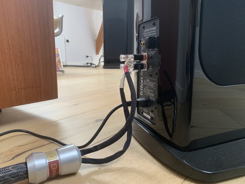
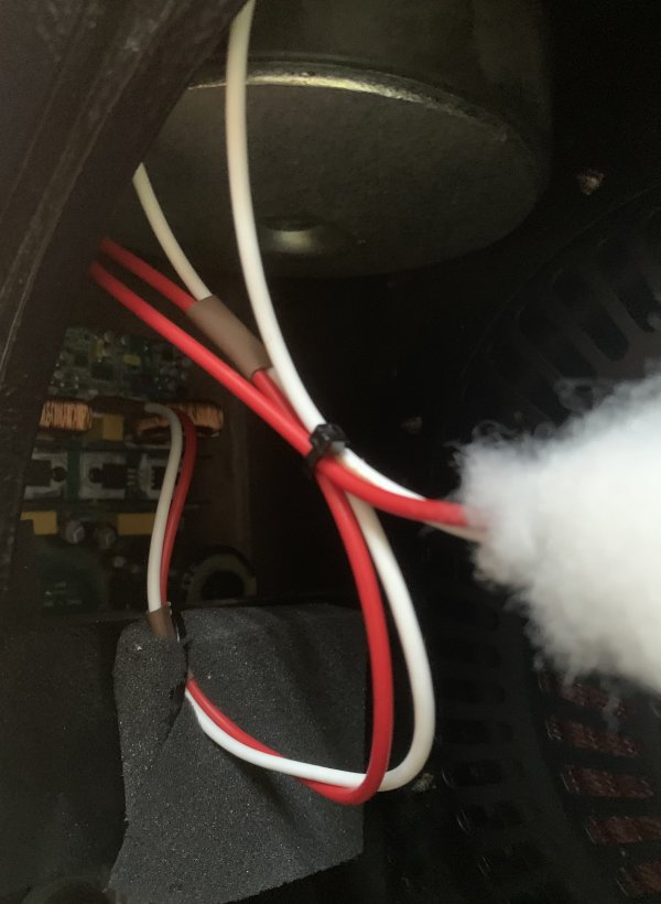
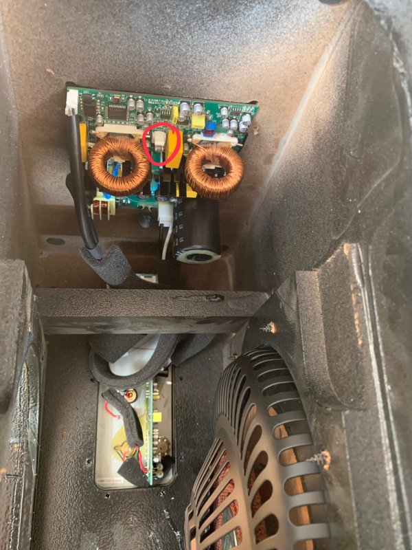
If you also replace the woofer wiring as I did (stripped Furutech) you have to solder on the connector for the output from the internal amp on the new wiring. I did it the easy way, and that is to cut the original wire 5cm or so from the connector, strip the wires, and then solder them to the new Furutech wires. The area where you solder the wires together must be insulated with two layers of heat-shrink tubing on each wire for safety. I did not take a picture of this, but one of the attached close up pics show the Furutech wires (red and white wires) going to the amp. Another close up shows the amp, and in a red circle the male part of the connector, the female part is on the wiring to the woofers.
This is all I can think of, in addition to what I have aready explained in previous posts. Hope it makes sense


 eti-research.com


