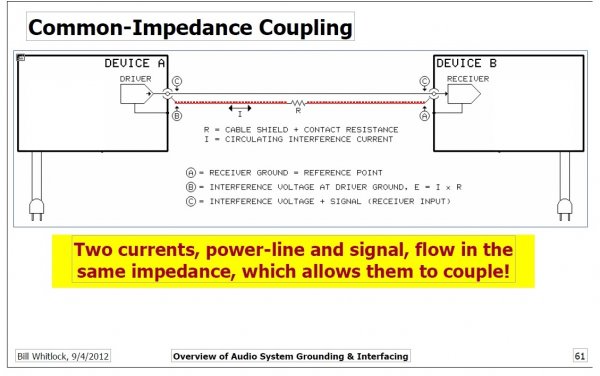
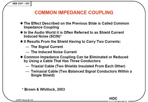
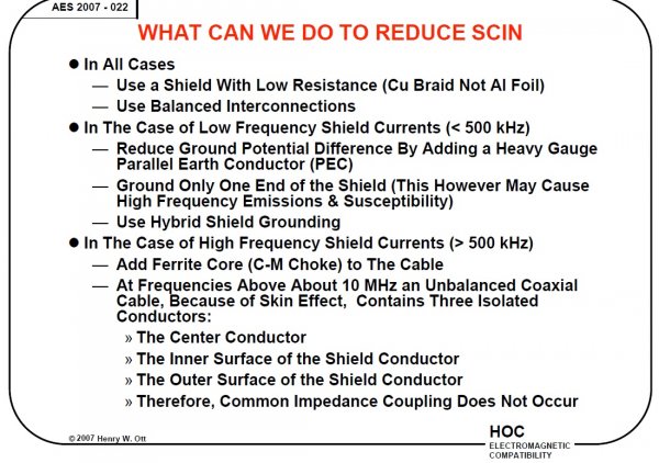
The title refers to this 2007 presentation by Henry Ott called "Audio interconnections & grounding - dispelling the myths"
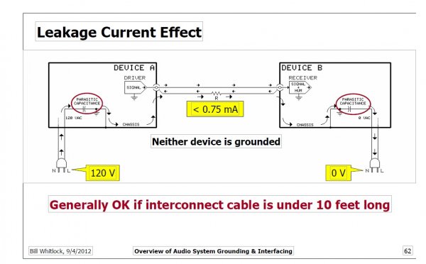
There is also another useful presentation, this time from 2012 by Bill Whitlock "An overview of Audio system grounding & interfacing"
I thought it worthwhile to start this thread as it applies to many discussions on this forum which involve grounding issues
So if you read both of these presentations you will see that there are a great number of considerations & aspects to electrical noise intrusion in audio devices which are interconnected.
Different considerations & approaches apply depending on the frequency of the noise & there is no hard boundary to this. In there words high frequency currents return to source via the path of least impedance whereas low frequency currents return via path of least resistance. This sounds simple but what defines high frequency Vs low frequency & is there a grey area in the middle where return currents will behave in either/both ways?
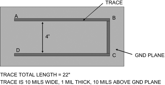
This is a well known rule in pcb design & it is easy to implement in most cases - assuming a solid ground plane on the bottom layer of a two layer pcb design, the HF currents return will be a roughly mirror image, on the ground plane, of the signal track on the top layer. It will not be as defined as the signal track but rather a statistical spread of return current with the highest density of current mirroring the shape of the signal track but also less density of current return pathways spreading out from this.
So here's a couple of diagrams to explain this:
First a simple U shaped traced over a ground plane
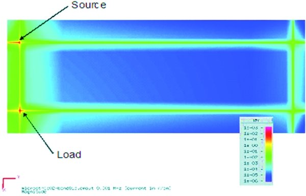
The measured return current for a 1Khz signal - color coded to show density of return current. As can be seen almost all the return current flows directly across the ground plane from A to D
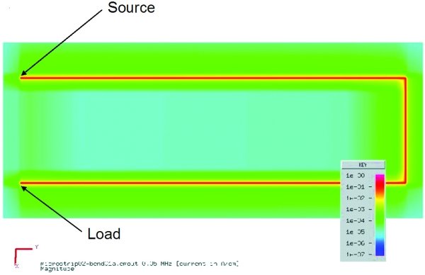
The measured return current for "intermediate" frequency signal
"shows current for a 50kHz signal flowing primarily along the signal trace (the wide green line following the path of the trace) and, to a lesser extent, directly from load to source (the fainter, wide, green line from the two ends of the trace) and in between. The middle area is light blue and not dark blue, indicating minimal current flow."
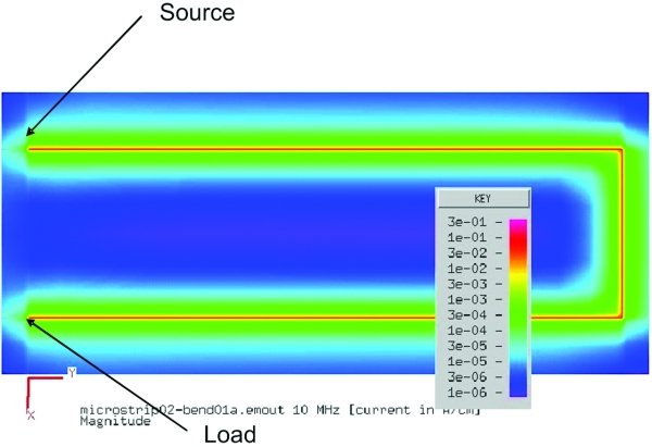
And finally return current for HF signal 1MHz - Virtually all the return ground current is flowing along the path of the signal trace.
So what's all this got to do with interconnecting audio devices?
This is the first principle of return currents - that different frequencies behave differently
So what happens when it's cables carrying signal & return currents between devices?
Just as an aside there are two considerations:
- what is the configuration to get the best, optimal audio environment for our interconnected audio devices?
- what is the best way to achieve optimal measurements when characterising a device & is this the same as above?
We can have device connection configurations which don't reveal any audible issues but when measured will show some measured noise.
More in following posts if there's any interest?
There is also another useful presentation, this time from 2012 by Bill Whitlock "An overview of Audio system grounding & interfacing"
I thought it worthwhile to start this thread as it applies to many discussions on this forum which involve grounding issues
So if you read both of these presentations you will see that there are a great number of considerations & aspects to electrical noise intrusion in audio devices which are interconnected.
Different considerations & approaches apply depending on the frequency of the noise & there is no hard boundary to this. In there words high frequency currents return to source via the path of least impedance whereas low frequency currents return via path of least resistance. This sounds simple but what defines high frequency Vs low frequency & is there a grey area in the middle where return currents will behave in either/both ways?
This is a well known rule in pcb design & it is easy to implement in most cases - assuming a solid ground plane on the bottom layer of a two layer pcb design, the HF currents return will be a roughly mirror image, on the ground plane, of the signal track on the top layer. It will not be as defined as the signal track but rather a statistical spread of return current with the highest density of current mirroring the shape of the signal track but also less density of current return pathways spreading out from this.
So here's a couple of diagrams to explain this:
First a simple U shaped traced over a ground plane

The measured return current for a 1Khz signal - color coded to show density of return current. As can be seen almost all the return current flows directly across the ground plane from A to D

The measured return current for "intermediate" frequency signal
"shows current for a 50kHz signal flowing primarily along the signal trace (the wide green line following the path of the trace) and, to a lesser extent, directly from load to source (the fainter, wide, green line from the two ends of the trace) and in between. The middle area is light blue and not dark blue, indicating minimal current flow."

And finally return current for HF signal 1MHz - Virtually all the return ground current is flowing along the path of the signal trace.

So what's all this got to do with interconnecting audio devices?
This is the first principle of return currents - that different frequencies behave differently
So what happens when it's cables carrying signal & return currents between devices?
Just as an aside there are two considerations:
- what is the configuration to get the best, optimal audio environment for our interconnected audio devices?
- what is the best way to achieve optimal measurements when characterising a device & is this the same as above?
We can have device connection configurations which don't reveal any audible issues but when measured will show some measured noise.
More in following posts if there's any interest?


