A Ground Isn't Just Rods

Kingrex

Well-Known Member
Feb 3, 2019
2,802
2,309
350
The thing is, I am that guy.

I may try a bunch more filters. But the fact that a loop forms with the dish itself sucks.
It shouldn't. Not if the panel is made up right and the dish equipment is grounded properly.
I do agree the component inputs to a TV can suck. I tried them with my TV to my surround system. In the end I ditched them and went with a HDMI connection that was much better. Maybe you can do like Wil and change the coax to ethernet. You could then try a Gigafoil if needed. I don't like the Gigafoil for audio, but it would do a fine job with a cinema system.
 

Folsom

VIP/Donor
Oct 25, 2015
6,024
1,490
520
Eastern WA
I’ll look into it to see if a conversion will work. SFP to ethernet would be nice. I’ll have to check the receiver. It already gets internet from ethernet.

I am not the only one. This is a known problem with these things.

The amp is just 2 channel, so it doesn’t take HDMI.
 

Kingrex

Well-Known Member
Feb 3, 2019
2,802
2,309
350
By the way Folsom, I had a bad amp that had internal ground issues . Thats an amp, not a source. My noise would not go away until the amp was rixed by Atmasphere.

If its electrically separate, I don't see how a ground issue could happen, but injected noise that is amplified could.

By the way, did you say if the hum is just there or it rises and falls with the volume. If its there consistently no matter the volume, its a ground issue. If it rises and falls with the volume, its not a ground loop. Thats for guest Folsom, I'm sure you know.
 

Folsom

VIP/Donor
Oct 25, 2015
6,024
1,490
520
Eastern WA
The amp is by a company that does AV stuff and links dozens of boxes together for commercial use. Pretty sure they ground correctly.

Here is someone else with basically the same issue. https://www.dbstalk.com/threads/buzz-hum-with-directv.227228/

It’s a mix of bad design for Satellite and TV. I might try a Brickwall/SurgeX to help. (I can make filters like that myself if I need) But really DirecTV should make better products knowing TV’s let it all through.
 

wil

Well-Known Member
Jul 22, 2015
1,482
1,507
428
By
Exactly. Some equipment needs to be isolated. Al was trying to isolate the power with a UPS type device. I do this too but I find the signal to be very important in some circumstances. That is why I said a mini DSP on the RCA or rebuild the power supply in the cable modem. Converting the coax to Ethernet sounds to be effective. How did you convert Wil. Do you have a stand alone box?
I may have misspoke about my set up. In more detail it's

Direct TV Satellite > coax > SWM switch box > coax > another splitter.
From there one coax goes to the DTV Receiver and the other to a box which connects to
my Modem via ethernet > Fiber converter > Fiber > converter > ethernet > Home Router.

The Audio ethernet goes to audio router > switch.

The idea is that the fiber section for the Home network (including DTV) isolates from
Audio.
 

Folsom

VIP/Donor
Oct 25, 2015
6,024
1,490
520
Eastern WA
Its not a given. Its a hope.
I’ve been inside it as well. I couldn’t see any obvious discrepancies. They wouldn’t have been able to sell them, especially with no balanced inputs, if they were problematic.
 

DonH50

Member Sponsor & WBF Technical Expert
Jun 22, 2010
3,947
306
1,670
Monument, CO
You need to be careful here. 2 grounds bonded at 2 different points in your electrical system as you have seen with audio can cause issue. It also means a lightning bolt to earth near your home is going up 2 ground sets to 2 different points in your electrical distribution and its at different voltages. This can create a strange swirl of hundreds of thousands of volts through the ground system of your home. You want these systems isolated from each other. I am not sure how to do this since there is 1 service. Unless your battery with the radio, and the charging power cord is unplugged during lightning events. The last ham radio I did I brought a #2 from a 1/4" x 2 x 8 bar at the radio station to the ground system in the main panel.
Just saw this and it is a very good point. Many places do not allow a second ground point for this very reason; it can be a hazard, and often it is against code. In my case, for the first trial (second rod for the audio system) I was able to provide measurements and supporting data to justify the additional rod, and it went to a sub-panel set up to control (as much as anyone can control) the ground path in the event of a strike. It had to be inspected and certified to meet the local electrical code. There were special requirements for grounding to ensure safety. It was not as simple as I made it sound (not just sticking a rod in the ground and wiring it up). When I moved it for the ham radio tower, it was next to the primary ground rod and tied to the main service panel so was not an issue -- but still had to be inspected, and the wiring had to be connected appropriately and properly gauged. Again, not as simple as adding a rod and hooking it up. I should have made that much clearer.

One thing that can be overlooked, aside from the dangers @Kingrex mentioned and the need to adhere to code, is that soil conditions can vary greatly even around a single building. If the added rod goes into poorly-conductive soil, it might not help. If it goes into highly-conductive soil but away from the main panel, it may create an unexpected (and undesirable, to say the least) path. If you do it yourself and the worst happens, your insurance company can deny coverage. Best left to experts.

Aside: At that time, I was a licensed electrician, had all the work inspected, and obtained certificates proving the work was done properly and code. These days, I no longer have the license, nor the time, and prefer to pay the experts to do their thing.
---
I have thoughts on phasing but will leave those for another thread since it is generally outside grounding. The components should not care, but there are load-balancing, surge demand, and safety issues that can arise to favor one or the other, especially with high-current loads. The safety ground is not usually an issue since both phases in nominal house wiring (at least in the states I have done it) to the same (or adjacent) outlets tie to the same neutral and safety ground bus bars in the service box.
---
Satellite dishes place a buffer amplifier at the dish, and thus have DC power as well as signal on the cable. One reason the world switched from RG-79 to RG-6 cables is that RG-6 uses a larger conductor to carry more DC current for the RF amp up there. But the whole thing can lead to an extra ground loop that causes noise, similar to cable boxes. My usual solution has been to use an RF isolator rather than audio isolator, a little device that goes inline of the RF cable rather than the audio cable. Usually works, but not always, natch. Some people have used an HDMI isolator, but finding those is harder IME and they do not always pass the full HDMI bandwidth (though cable boxes are still on the low end -- at least in my area there are no 4K cable boxes available).
 
Last edited:

cjf

Well-Known Member
Nov 19, 2012
452
101
948
Nice topic and something I've been thinking about over the past few years (ie..proper grounding).

A few questions come to mind after reading the thread:

On the topic of earth (soil..etc) resistivity and its relation to achieving proper grounding, specifically related to using the "4 Point Method" if in bad soil, would you say the issue here with this option is the common lack of space/acreage on ones property to build a big enough 4 point ground rod system that can overcome the bad soil? If so, is there an ideal minimum of space required to build such a system that could possibly help, in a big way, the soil issues?

I've been under the impression that the "material" (more soil, bedrock, clay..etc) that the tip of the ground rod comes in contact with at the end of the rod which is under the surface should also be electrically conductive. Does the tip matter as much or less than the greater outer area of the rod in contact with the earth on its way to the stop point in the ground?

Giving an example of a property I own which I will be building a house on the next few years, its located on fairly shallow sandy soil with granite bedrock below. My guestimate based on GPR survey results (Ground Penetrating Radar) of the property is that bedrock is only about 5-6ft below the surface of my home site pad. This soil and bedrock type combination has me wondering if I will need to plan for "alternative" grounding plans as this combo sounds like it may have high electrical resistance levels. The soil type is a known issue in general and based on my own research, granite is not a very good conductor of electricity ( both of which are involved in my case here).

But with that said, I do have some acreage outside of the site pad which should be sufficient to accommodate a 4 point grounding system short of it needing to span more than 20acres. The question here being, with enough acreage in bad soil can this potential issue be overcome with enough space to do so?

An interesting article about good grounding options in bad soil::::

 
Last edited:

wil

Well-Known Member
Jul 22, 2015
1,482
1,507
428
Nice topic and something I've been thinking about over the past few years (ie..proper grounding).

A few questions come to mind after reading the thread:

On the topic of earth (soil..etc) resistivity and its relation to achieving proper grounding, specifically related to using the "4 Point Method" if in bad soil, would you say the issue here with this option is the common lack of space/acreage on ones property to build a big enough 4 point ground rod system that can overcome the bad soil? If so, is there an ideal minimum of space required to build such a system that could possibly help, in a big way, the soil issues?

I've been under the impression that the "material" (more soil, bedrock, clay..etc) that the tip of the ground rod comes in contact with at the end of the rod which is under the surface should also be electrically conductive. Does the tip matter as much or less than the greater outer area of the rod in contact with the earth on its way to the stop point in the ground?

Giving an example of a property I own which I will be building a house on the next few years, its located on fairly shallow sandy soil with granite bedrock below. My guestimate based on GPR survey results (Ground Penetrating Radar) of the property is that bedrock is only about 5-6ft below the surface of my home site pad. This soil and bedrock type combination has me wondering if I will need to plan for "alternative" grounding plans as this combo sounds like it may have high electrical resistance levels. The soil type is a known issue in general and based on my own research, granite is not a very good conductor of electricity ( both of which are involved in my case here).

But with that said, I do have some acreage outside of the site pad which should be sufficient to accommodate a 4 point grounding system short of it needing to span more than 20acres. The question here being, with enough acreage in bad soil can this potential issue be overcome with enough space to do so?

An interesting article about good grounding options in bad soil::::

I connected ground to 16’ of copper rod in a horizontal trench filled with a bentonite clay slurry. It give a low impedance ground and never dries out. No need to be concerned about soil type.
 
  • Like
Reactions: cjf

Kingrex

Well-Known Member
Feb 3, 2019
2,802
2,309
350
A 4 Point Method is a way to test the impedance of the earth. 4 probes are inserted into the earth in numerous places around your property and a current is injected into one and the other 3 are used to measure. That information is then sent to a lab at Lyncole and they give me an engineered plan to obtain a 5 ohms earth ground impedance system. It's generally some amount of chemical ground rods tied together with 2/0 copper wire.

You can also do like Wil and get bags of Bentonite clay and pot a piece of 2/0 copper 20 feet long in it.

Chemical ground rods are about $2400 a piece. They are nice as you charge them with a special epsom salt than pulls moisture from the air, then leaches it out weep holes in the tube to make the ground more inductive.

Remember, a ground is more about shunting transient voltage spikes. Wil pulled his ground apart by accident and heard nothing . I have heard nothing pulling mine. The real magic is more about how the wiring is managed in the panel. That can be heard. At times very noticeable. Other times not so much. Lots of variables involved there.

If your building a house, they will install a Ufer ground. They are generally very good. There are ways to improve upon them.
 
  • Like
Reactions: Atmasphere and wil

cjf

Well-Known Member
Nov 19, 2012
452
101
948
A 4 Point Method is a way to test the impedance of the earth. 4 probes are inserted into the earth in numerous places around your property and a current is injected into one and the other 3 are used to measure. That information is then sent to a lab at Lyncole and they give me an engineered plan to obtain a 5 ohms earth ground impedance system. It's generally some amount of chemical ground rods tied together with 2/0 copper wire.

You can also do like Wil and get bags of Bentonite clay and pot a piece of 2/0 copper 20 feet long in it.

Chemical ground rods are about $2400 a piece. They are nice as you charge them with a special epsom salt than pulls moisture from the air, then leaches it out weep holes in the tube to make the ground more inductive.

Remember, a ground is more about shunting transient voltage spikes. Wil pulled his ground apart by accident and heard nothing . I have heard nothing pulling mine. The real magic is more about how the wiring is managed in the panel. That can be heard. At times very noticeable. Other times not so much. Lots of variables involved there.

If your building a house, they will install a Ufer ground. They are generally very good. There are ways to improve upon them.
Hello and thanks for the details.

The Ufer ground sounds like an interesting option. Doing a quick read of what it is I see mention of these systems being installed, when doing a new build, at the same time as the concrete footer is being done. There is mention of the system utilizing the large area of damp soil typically found at this part of the foundation and the concrete itself soaks up this moisture to help in the grounding process.

I'm curious if the system would be as effective if one was using a thick vapor barrier between the soil and the concrete footer/slab itself in an effort to greatly reduce the amount of moisture that the concrete is exposed to? Maybe if that is the plan a Ufer system not baked into the footer/slab would be a better option (ie..treating its installation as an after thought vs it being part of the original design).

An example of the vapor barrier I'm thinking of in this example:


Thanks again
 

cjf

Well-Known Member
Nov 19, 2012
452
101
948
I connected ground to 16’ of copper rod in a horizontal trench filled with a bentonite clay slurry. It give a low impedance ground and never dries out. No need to be concerned about soil type.
Hello, I'm curious if you are located in an area that see's average or possibly better than average levels of rainfall each year (in inches)?

In my area, we only get about 10-13" of rainfall per year. So I wonder how much your rainfall levels are contributing to the bentonite clay not drying out and requiring owner involved maintenance?

Thanks
 

Kingrex

Well-Known Member
Feb 3, 2019
2,802
2,309
350
Hello and thanks for the details.

The Ufer ground sounds like an interesting option. Doing a quick read of what it is I see mention of these systems being installed, when doing a new build, at the same time as the concrete footer is being done. There is mention of the system utilizing the large area of damp soil typically found at this part of the foundation and the concrete itself soaks up this moisture to help in the grounding process.

I'm curious if the system would be as effective if one was using a thick vapor barrier between the soil and the concrete footer/slab itself in an effort to greatly reduce the amount of moisture that the concrete is exposed to? Maybe if that is the plan a Ufer system not baked into the footer/slab would be a better option (ie..treating its installation as an after thought vs it being part of the original design).

An example of the vapor barrier I'm thinking of in this example:


Thanks again
A Ufer is NEC required and they will install one if your building new. If your adding onto the house and they pour foundation, be sure to ask for one to be added.

Vapor barrier is an absolute NO. I completely defeats the ground. Thats like saying you want to wrap your ground rods in an insulated jacket before burying them.
 

Kingrex

Well-Known Member
Feb 3, 2019
2,802
2,309
350
When I say there are ways to improve upon something, I am relying on 28 years experience. I am knowledgeable about methods and materials that are recognized and approved by governing bodies. I am not trying to reinvent the wheel. I don't encourage others to try and do as such. I encourage you to read to try and understand so your educated and can ask good questions of the installer. But you have to be aware there is a lot of erroneous information out there too.
 
  • Like
Reactions: MarkusBarkus

wil

Well-Known Member
Jul 22, 2015
1,482
1,507
428
Hello, I'm curious if you are located in an area that see's average or possibly better than average levels of rainfall each year (in inches)?

In my area, we only get about 10-13" of rainfall per year. So I wonder how much your rainfall levels are contributing to the bentonite clay not drying out and requiring owner involved maintenance?

Thanks
Yes, We get avg 49” rain/year. In your case some watering from a garden hose once a month might be in order.
 

Kingrex

Well-Known Member
Feb 3, 2019
2,802
2,309
350
Nice topic and something I've been thinking about over the past few years (ie..proper grounding).

A few questions come to mind after reading the thread:

On the topic of earth (soil..etc) resistivity and its relation to achieving proper grounding, specifically related to using the "4 Point Method" if in bad soil, would you say the issue here with this option is the common lack of space/acreage on ones property to build a big enough 4 point ground rod system that can overcome the bad soil? If so, is there an ideal minimum of space required to build such a system that could possibly help, in a big way, the soil issues?

I've been under the impression that the "material" (more soil, bedrock, clay..etc) that the tip of the ground rod comes in contact with at the end of the rod which is under the surface should also be electrically conductive. Does the tip matter as much or less than the greater outer area of the rod in contact with the earth on its way to the stop point in the ground?

Giving an example of a property I own which I will be building a house on the next few years, its located on fairly shallow sandy soil with granite bedrock below. My guestimate based on GPR survey results (Ground Penetrating Radar) of the property is that bedrock is only about 5-6ft below the surface of my home site pad. This soil and bedrock type combination has me wondering if I will need to plan for "alternative" grounding plans as this combo sounds like it may have high electrical resistance levels. The soil type is a known issue in general and based on my own research, granite is not a very good conductor of electricity ( both of which are involved in my case here).

But with that said, I do have some acreage outside of the site pad which should be sufficient to accommodate a 4 point grounding system short of it needing to span more than 20acres. The question here being, with enough acreage in bad soil can this potential issue be overcome with enough space to do so?

An interesting article about good grounding options in bad soil::::

If your going to build a new home and install a listening room, you should reach out well before you start. Your somewhat barking up the wrong tree when it comes to premium power to an audio system. Its not so much about the ground in the earth. It more about the panels and wiring in the home. The earth ground itself is more about safety. A earth ground is a diminished return when it comes to $ spent on audio. It needs to be right, don't get me wrong. But its not how to find great audio performance.

There is some bedrock that has enough metal in it to be conductive. I have seen a project where 20 holes were boored 40 feet deep and chemical rods dropped inside. It was such a good ground it draws lightinig from around to it.

I know another job where the army corps and their big ego boys designed some super ground. It read well over 100 ohms. They spent about $100k plus to put it in. They installed it over an ancient stone river bed. The single rod at the service was about 10 ohms.

Most location can be effectively grounded. A reading can be taken at the site and a guarenteed ground can be provided. But that is a lot of money.
 
  • Like
Reactions: Atmasphere

MarkusBarkus

Well-Known Member
Feb 6, 2021
991
1,632
228
66
Its not so much about the ground in the earth. It more about the panels and wiring in the home. The earth ground itself is more about safety.
...I agree 100% on the good wiring concepts. As the "Tower of Power" *still* sings: You can't cut loose without that juice!
 

Atmasphere

Industry Expert
May 4, 2010
2,336
1,837
1,760
St. Paul, MN
www.atma-sphere.com
@Kingrex is correct when maintaining his position on the wiring in the panel.

Grounds are for safety. They should not be affecting the sound. If they do, its a serious sign that the designer of your audio equipment thus affected really hasn't thought the whole grounding thing thru. Its serious business and has to be done right. Despite how complex grounding can be, getting the grounding right in audio equipment really isn't that hard so its really saying something when someone gets it wrong.
 

Kingrex

Well-Known Member
Feb 3, 2019
2,802
2,309
350
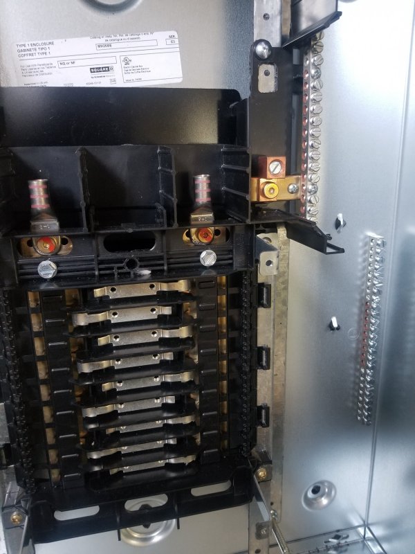
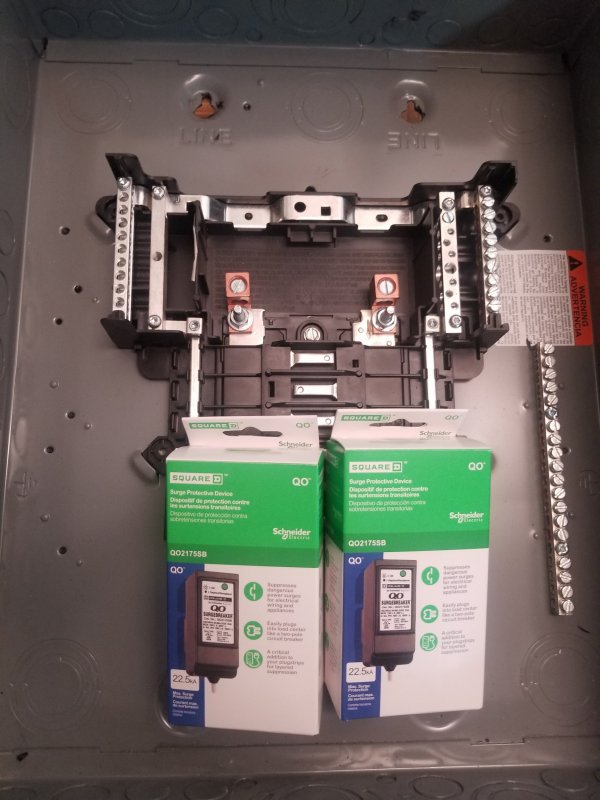
This is audibly more impactful than an earth ground. This SqD NQ pannelboard is 100% copper when I am done with it. This should be the foundation of every home with an audio system. The utility terminates in here. From this panel, you distribute power to an inexpensive SqD Homeline panel to feed all the lights and receptacles. Your audio can come from the NQ, or a subpanel.

You can drop a pair of SqD QO surge protection devices right into the main NQ panelboard, or the all copper (after I am done modifying it) QO subpanel loadcenter you see them sitting in

If your in Texas or Florida, you might want a Richard Gray Power Company surge protection in the NQ panel and the SqD QO surge protection in the subpanel.

A good ground in the yard will definitely help the surge protection devices shunt a surge to ground. That is the earth grounds primary purpose.
 

Attachments

  • 20221006_100029.jpg
    20221006_100029.jpg
    681 KB · Views: 22
  • 20221006_100731.jpg
    20221006_100731.jpg
    568.5 KB · Views: 22

About us

  • What’s Best Forum is THE forum for high end audio, product reviews, advice and sharing experiences on the best of everything else. This is THE place where audiophiles and audio companies discuss vintage, contemporary and new audio products, music servers, music streamers, computer audio, digital-to-analog converters, turntables, phono stages, cartridges, reel-to-reel tape machines, speakers, headphones and tube and solid-state amplification. Founded in 2010 What’s Best Forum invites intelligent and courteous people of all interests and backgrounds to describe and discuss the best of everything. From beginners to life-long hobbyists to industry professionals, we enjoy learning about new things and meeting new people, and participating in spirited debates.

Quick Navigation

User Menu

Steve Williams
Site Founder | Site Owner | Administrator
Ron Resnick
Site Co-Owner | Administrator
Julian (The Fixer)
Website Build | Marketing Managersing