Multigig modem/router mod project

Xymox

Well-Known Member
Apr 16, 2019
330
279
150
www.appletvx.com
ATTENTION:

I want to make sure everybody is aware of the complexity of a Mikrotik router. These DO NOT come ready to go out of the box. These are made for IT guys/gals.. I have used them for so long I forget they are complex for new people. PLUS how they get setup for each user and config is a bit different. Ubiquiti is just plug it in and your done. Mikrotik is not like that at all. Well, not for the routers in the high end. They have home routers that are plug and play, but, these routers we are playing with are meant for ISPs and serious IT pros, so they come with a blank config.

I will work up a tetorial for how to set one up that anyone can follow. Also I can make a config file you can drop on it that will set it all up for our type of use.. The Mikrotik web site has a community forum, and wiki and lots of videos on how-to..


RouterOS is a serious, adaptable router OS.. BUT that comes with a downside, 400 trillion config settings, tools and applications.

So.. You have been warned.. Its a complex device. It can be made super easy tho with just dropping a config file on it and going from there.
 

Xymox

Well-Known Member
Apr 16, 2019
330
279
150
www.appletvx.com
SO I have completed the look over of the router and I am ready to order parts...

Im excited.. This router is way cool for modding.. Super clean and super easy to mod. Its easy to get apart and work on. Took me 2 mins, literally, to take it apart completly the first time. Its very high quality build. It has lots of spacing on the PCB so noise is fairly isolated. The switching regulators actually have reasonable caps to start with.

SO lets dig in..

Its VERY simple. Has almost no parts. All the ports are hooked to a single chip, a Marvell 98PX1012. I will locate more info on this chip. This will be a primary target as all packets are processed by this chip. It develops all the signals and clocks for the ports. The CPU is interesting, a Annapuralabs ARM chip its a 4x ARM Cortex-A57 at 1.7Ghz. A AL-324

Then its all just PWM voltage regulators as discussed above. MUCH better quality then the ones used in the modem tho and way better thought out. EVERYTHING gets its own regulation. Thats pretty cool. Isolated. So there are 3 regulators for various things at 3.3V for example. They could have used one supply for all three devices, but, they decided to use 3 for better regulation.

There are a lot of these regulators. 3 x 3.3V, 2 x 1.7V, 4 x 1.0V, 0.86V, 1.2V, 2.5V and the main 12V which feeds them all. For a total of 12 regulators. So lots of caps..

I took a LOT of pics.. Downloadable zip..

Overall pics..


Cool heatpipe.. The switch chip gets hot tho and I might look into how to get this heatpipe to also fit on the switch chip.


CPU:


Switch chip


You can see 5 of the regulators here and the input power.. YES they left off caps.. BUT good place for new ones :)


__________________________________________________________________________________________________________________________________


So.. I did config and hooked it up and ran it over night. I wanted to get a feel for performance and config. Its just awesome. REALLY powerful. I was able to pull 8 Gbps thru it with NAT and Firewall rules. Hooked up great with the S33 modem and established a 2.5 Gbps link... By provider has not turned on multigig yet but I can now hit eve so slightly higher then 1Gbps with over-provisioning. I get 1.1Gbps. Jitter is nearly unmeasurable. BUT I will do more measurements on that later..

My main concern has been the fans. They scare me. When you process 10Gbps its impossible to not have fans tho. Its important to have a dead quiet router for a lot of people. WELL I was surprized. They never came on in my use. BUT I only have 5 1G Ethernet SFP modules and 1 Multirate SFP+ module. Plus I am not pulling tons of data thru it. I did force the fans on tho and was really surprized, they are really quiet in their first stage mode. The fans will be something I want to look at. I would like to eliminate them completely. By putting the switch chip on the heat pipe and using a external linear supply, it looks possible to never have the fans even come on if the number of SFP+ modules is kept low.. There are many options tho for a really quiet fan in this form factor.


SO... I will go ponder up a Mouser caps order.. Again its all about tant caps for this phase of things..

Im also looking at grounding. The SFP+ ports look pretty easy to run serious grounding to internally.

I want to use RF absorbing material around the voltage regulators to suppress the RF coming from the coils.

Overall vibration dampening is something I will look at as well. The case might need some things..
 
Last edited:

Kingrex

Well-Known Member
Feb 3, 2019
2,914
2,393
350
Very interesting upgrade. Just to be clear, is this unit an all in one modem and router. Or are you working on just a router. I use a SB8200 3.1 and an Asus RT AC5300. Once I went separate it was a massive upgrade over an all in one. But your using a much more robust system. And to be honest. When I upped my internet with Comcast from 300 mbps to gigabit, I did not hear the difference. What I do hear is better power supplies and better cables. As well as physically isolating the units from vibrations. I gather what I am really doing is reducing jitter. Jitter seems to be the enemy.
Curious if my router is good for music. I know its fast, but not sure if the chip is quiet and jitter free.
Rex
 

Rob181

Well-Known Member
Oct 1, 2014
207
116
275
Very interesting upgrade. Just to be clear, is this unit an all in one modem and router. Or are you working on just a router.
Rex

If you had read the thread - you would know the answer to this question.
 

Xymox

Well-Known Member
Apr 16, 2019
330
279
150
www.appletvx.com
Very interesting upgrade. Just to be clear, is this unit an all in one modem and router. Or are you working on just a router. I use a SB8200 3.1 and an Asus RT AC5300. Once I went separate it was a massive upgrade over an all in one. But your using a much more robust system. And to be honest. When I upped my internet with Comcast from 300 mbps to gigabit, I did not hear the difference. What I do hear is better power supplies and better cables. As well as physically isolating the units from vibrations. I gather what I am really doing is reducing jitter. Jitter seems to be the enemy.
Curious if my router is good for music. I know its fast, but not sure if the chip is quiet and jitter free.
Rex

I am indeed using a new modem. A new gen of the Broadcom BCM3390 modem chip that powers the 8200. I am modding the router and modem... I am a firm believer in a seperate modem / router / access point approach. This is a lot more complex and a lot more money tho.

GOOD QUESTION.. Do the mods make a difference for sound quality to streaming music from the internet.. I am not sure yet. That is also what this thread is about. Its possible. Reducing jitter & RF noise sure could have dramatic effects.. I think milage may vary tho for each person because of a huge number of factors..

Its going to be interesting....
 

Xymox

Well-Known Member
Apr 16, 2019
330
279
150
www.appletvx.com
I have completed the first rounds of ruff exploratory mods on the modem.

I have been doing mods on modems and routers for networking performance improvements for a really long time. My first one was in 1991.. SO I am celebrating 30 years of modding modems with this mod.. These mods were for networking performance and not really for SQ improvements tho. This long experience doing this created a lot of knowledge of cable modem technology.. Its stunningly gnarly. DOCSIS 3.1 is crazy..

To understand why my mods matter and what they accomplish a bit of understanding of a cable modem system is a good idea. I will try and explain it in a easy to follow manner.. You could skip this..

_________________________

A cable modem uses a very complex way of sending VAST amounts of data thru a coax. Think of a light bulb going on/off. That on/off pattern can convey a message. Dots and dashes of Morse code can communicate really well using just a dot/dash or a on/off. Now if you had 2 light bulbs at the same time, you could communicate twice as much or twice as fast. QAM Modulation uses a frame of 256 light bulbs at once and these lights go on/off incredibly quickly.. A DOCSIS 3.1 cable modem typically uses 32 channels of these 256 light bulb frames. This is a whopping 8,192 light bulbs going on/off millions of times a second. The newest modulation has 4096 light bulbs per "frame", this is OFDM. A gigabit, and soon multigigabit, connection combines the 32 QAM 256 channels and the OFDM channel. There can even be 2 OFDM channels. The modem then keeps track of aprox 17,000 modulated points each turning on/off millions of times a second. Any of these lights could get blocked by noise and fog, delayed more then the others or skewed in big groups. There are not really light bulbs, its just a analogy. They are modulated points.

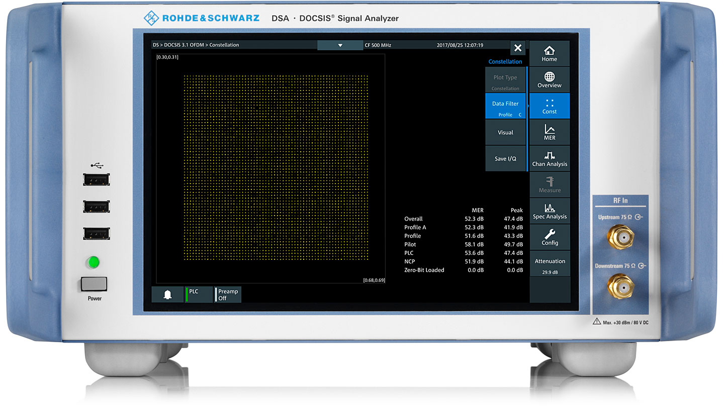
A nice tester showing a "constellation" of the OFDM 4096 points.. They look like little lights..


Its a technology wonder. Its incredible it works at all.

If your interested in a deep dive into DOCSIS, like PHD level deep dive off the deep end.. This is a nice starting off point..

So.. your Tidal byte comes along to the cable company. It reaches a CMTS ( Cable Modem Termination System ) which is a million $ device that takes your byte of music and spreads it out over all those 17,000 points. It does this with all sorts of crazy math and the whole thing has to be tolerant of all sorts of crap and noise between you and the CMTS. The math involved is staggering... Ultimately a spectrum of carriers ends up on the coax.. It goes thru all sorts of junk between the CMTS at the cable co head end all the way to your house and thru your wires and splitters to your cable modem..

The cable modem then has to sync up clocks so that every light bulb, all 17,000 of them, going on/off millions of times a second, is EXACTLY locked. It has to error correct this massive bit stream. It has to watch for just the frames intended for YOUR modem because it also has typically 300 other people on it at the same time sharing these same sets of lights.. It then reassembled your byte from Tidal from all those modulated points. It then also does error detection and correction of your Byte from Tidal. It buffers and then clocks and spits out the byte thru the ethernet port..

_______________________________

OK with that out of the way.....

Modems are made as cheaply as possible. They just need to pass CableLabs certification. ZERO extra engineering is done beyond that.. Good enough,, is the standard.. SO its pretty easy to improve performance.. Jitter, RF noise, Power supply stability are all of no concern at all during design beyond "does it work or not...

I have done all this before..

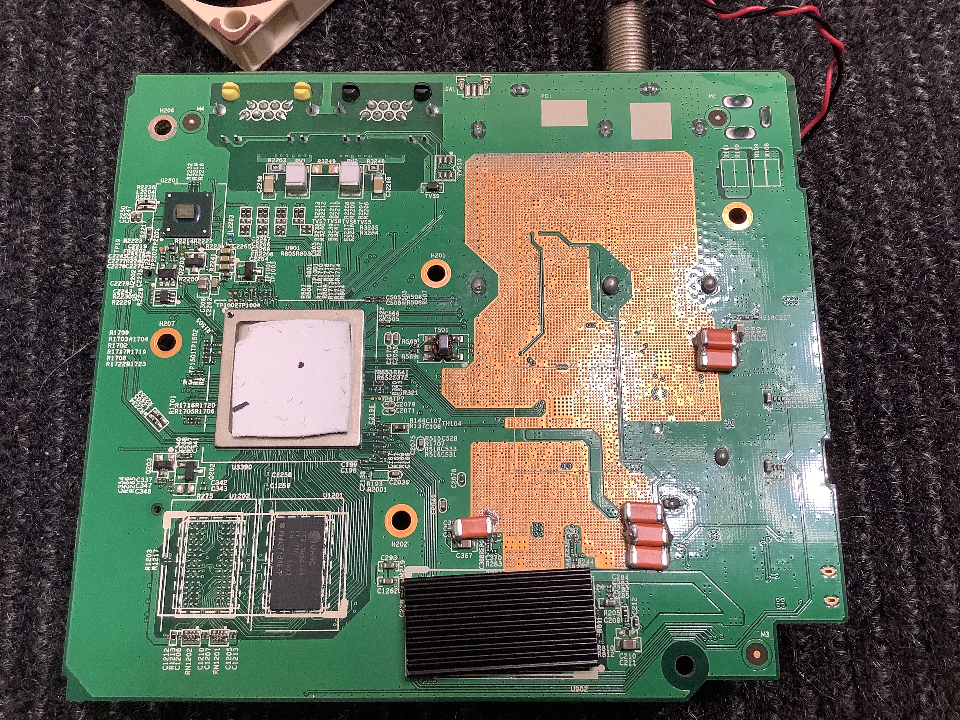
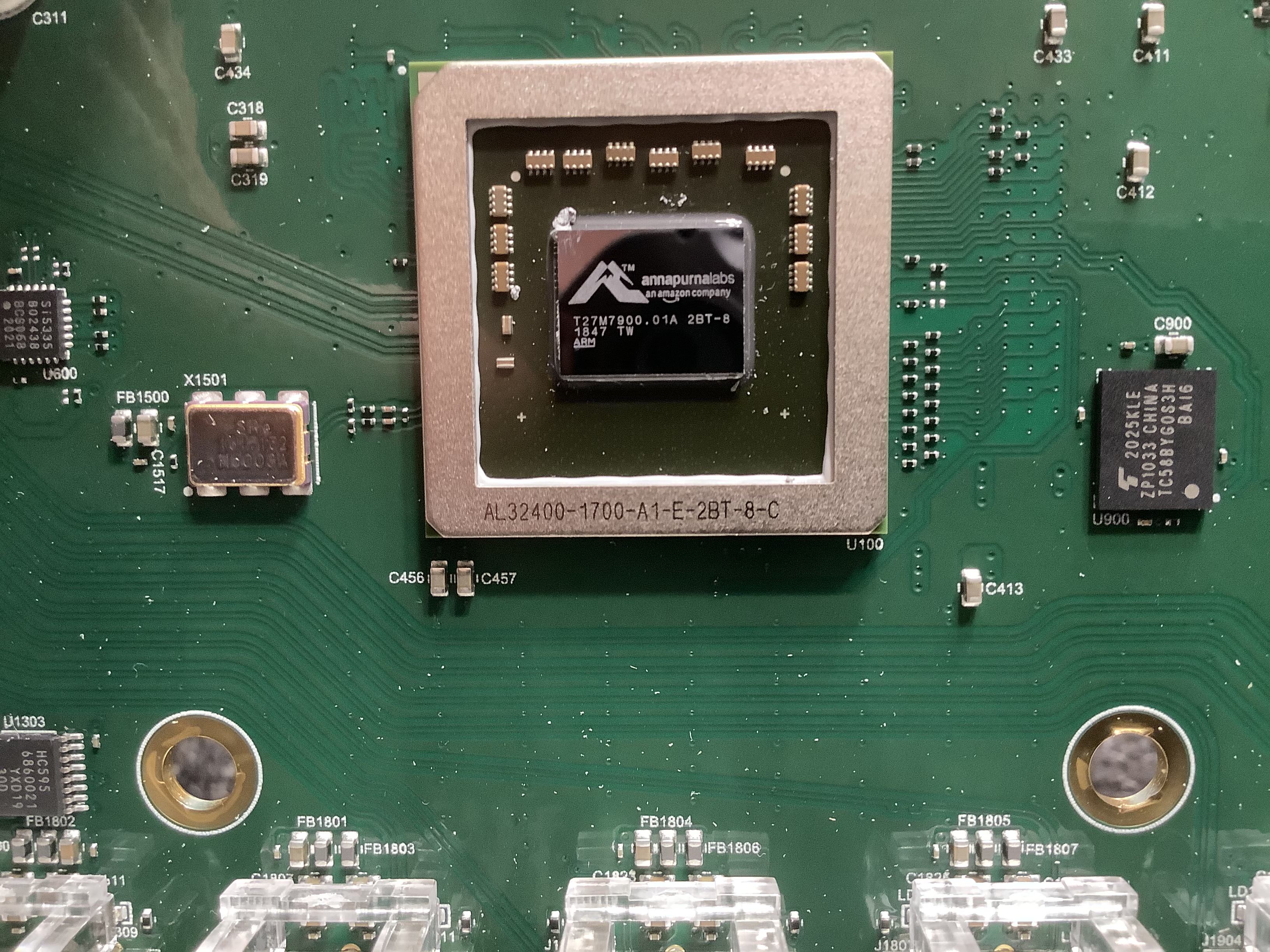
So I ended up adding almost 1000uF to the 3.3 V supply. This is because its really the main supply. The BCM3390 chip which does all the demodulation - it wacthes the 17,000 lights - and does the decoding and even clocks the ethernet ports. The power supply caps there originally were aprox 0.1uF. So I increased this filtering by 10,000 TIMES. This completly eliminated any RF on the supply because I used tantalum caps. This also stabilized the supply very seriously. As its A/D section that does the decoding and the D/A that creates the upstream lights is all done from this supply, doing this vastly helped clean up the A/D and D/A sections. Also as the decoding and stuff on the CPU goes on the supply stays very stable in voltage making the D/A and A/D far more accurate. The light bulbs became far easier to see and it made the outgoing lights more precise. AGain the "lights" are a anology, they are really modulated points..

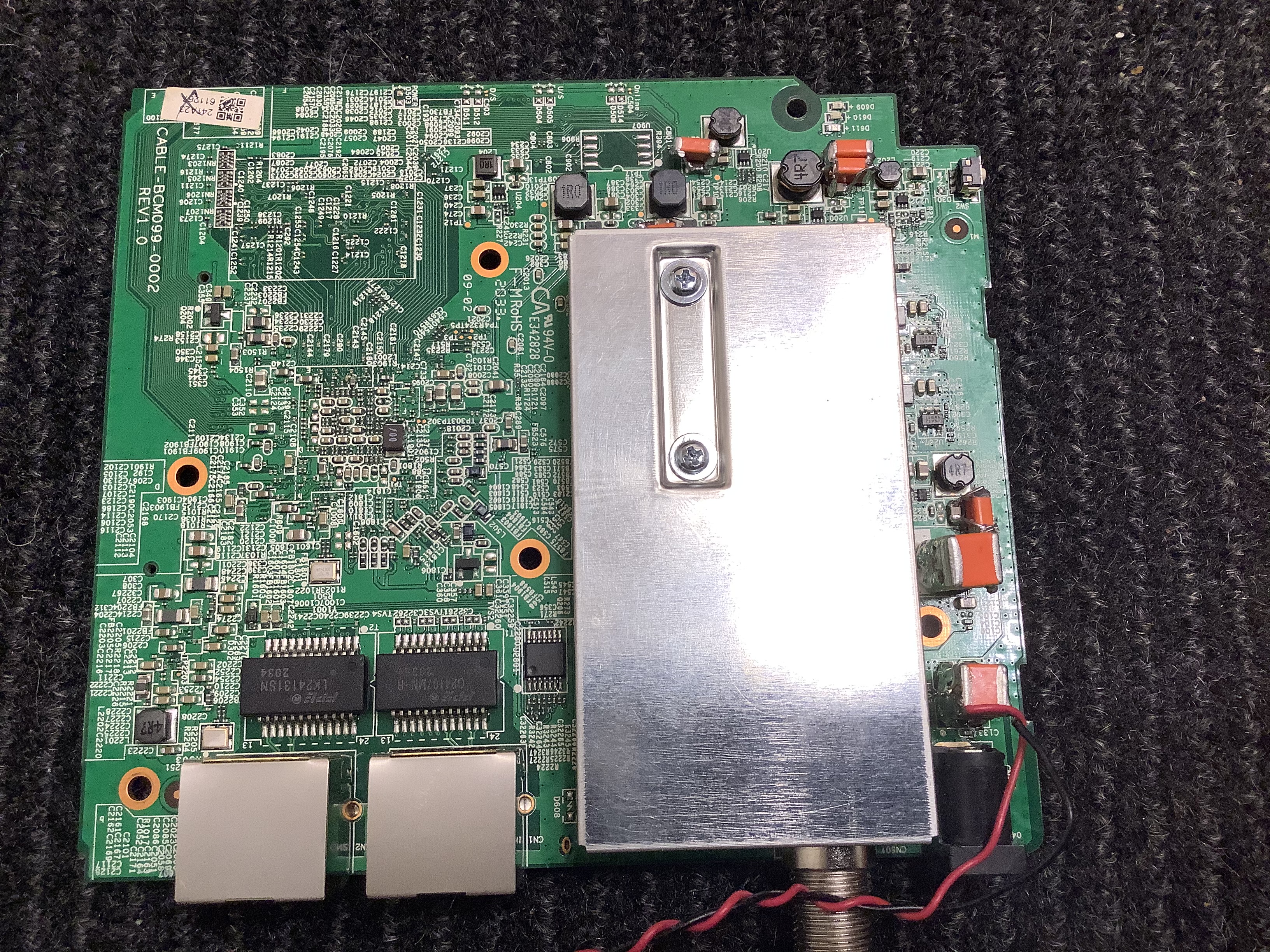
I then turned to the RF section. This is a preamp and a amp.. This is a critical section as any noise across the whole band from 5Mhz to 1200Mhz causes issues.. There are 2 chips in this section. One a preamp and one a amp. the 5V supply feeds all this. I dropped 660uF of tantalum on this. It had the same 0.1uF to start with. So I increased the filtering by 6,600 times. Again the result was no noise I could measure with the spectrum analyzer. A 35db reduction in RF noise.. ALSO there is a transmitter chip here. Its a amp.. This amp transmits the 17,000 light signals back to the cable company. Its a damn important transmitter. Just like with a audio amp, big caps stabalize the amp and make the supply much quieter in operation. So the amp has a better noise floor and more precise modulation.

I hit the other supplies even tho they were not as important. They all got a 330uF cap. So 3,300 times better filtering...

On the 12V input side.. Sadly.. There is ZERO room for a good audio cap inside the case. So this will need to be done outside the case from a nice linear supply. WHat I did do was extreme tho. I stacked up tant caps for a total of 2000uF across the 12 supply. 2000uF of tantalum is just excessive and overkill, but, its all about overkill right ?

SO.. Overall the unit now has vastly reduced RF noise. What is left is radiated by the coils in the voltage regulators and this seeps back into the electronics.. I will think about small shields...

OK SO....

Indeed it effected performance.. The cable modem gained 3db of S/N ratio reported on its status page. That was the biggest improvement in S/N I have seen in any mods. Also, interestingly signal lock when firt booted is now clearly faster. The corrected errors are less. The MER is lower.. No doubt because of the vastly lowered noise floor for A/D and D/A...

Jitter and latency performance improved. This is because it has a better connection to the CMTS and has to do less error correction.

The networking improvements are minor. Like 10%. But aren't we all after that last 10% ?

I know someone way up on the technical side at my ISP and I asked him to look at it from their side as they have way better tools. What he saw was the best numbers he had seen on any device. This is normal for me tho, this happens with any modem when modded correctly. Its easy actually as they start out as crap...

SO does any of that matter ? In normal use ? Not really. Not for any normal people. That is why cable modem makers dont do it. I dropped $100 in tant caps into it and that had no real effect for any normal use.. YES it might work better in situations with really bad connections.. But thats about it.. I do it, well,,,, just because I can,,, hahahaha... Its fun having the best cable modem on earth...

OK so I don't know on sound quality yet.... That will have to come later... I need to do the router as well and then swap in both and really spend time doing a A/B....


Chart showing jitter and latency before and after..


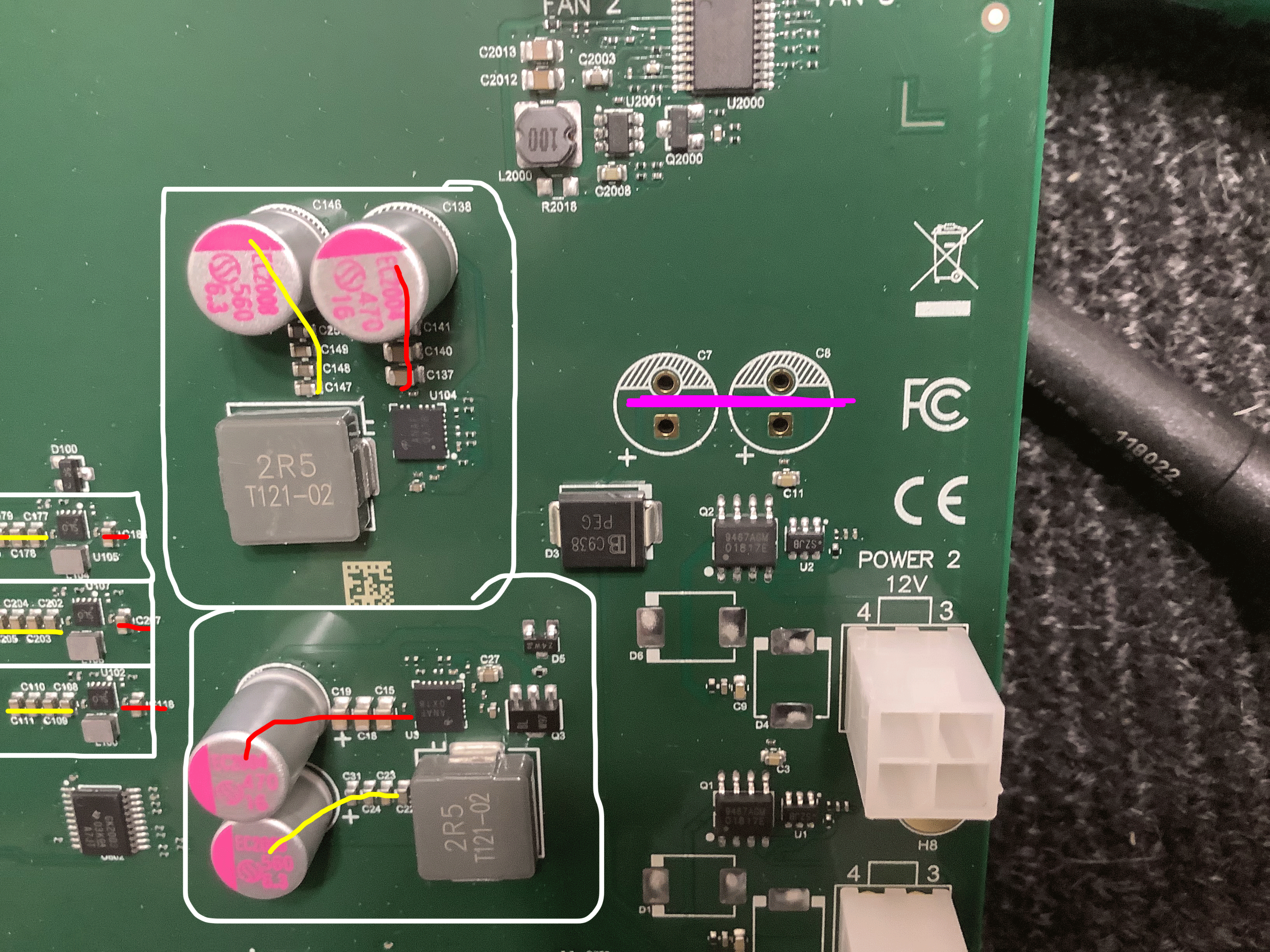
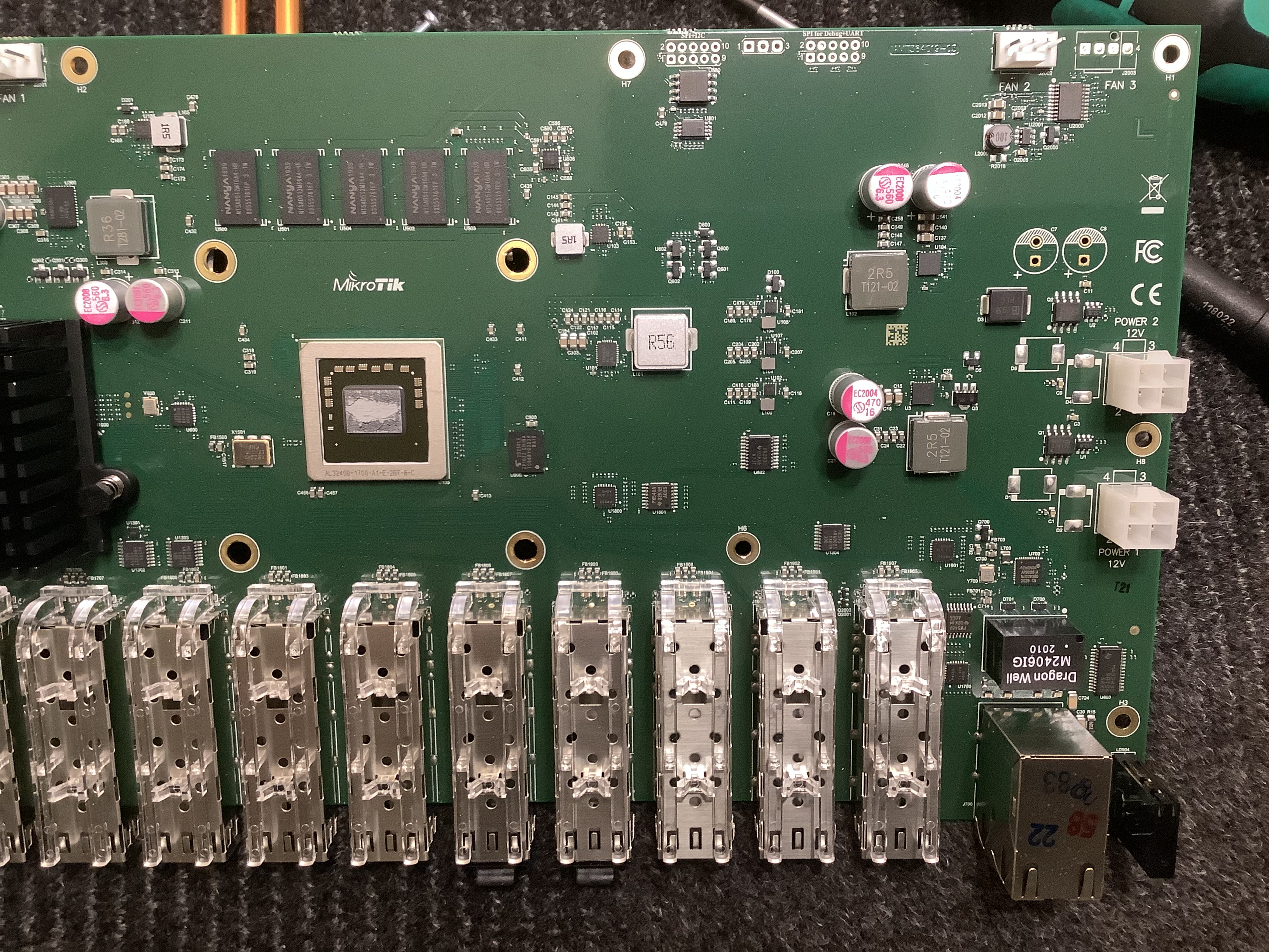
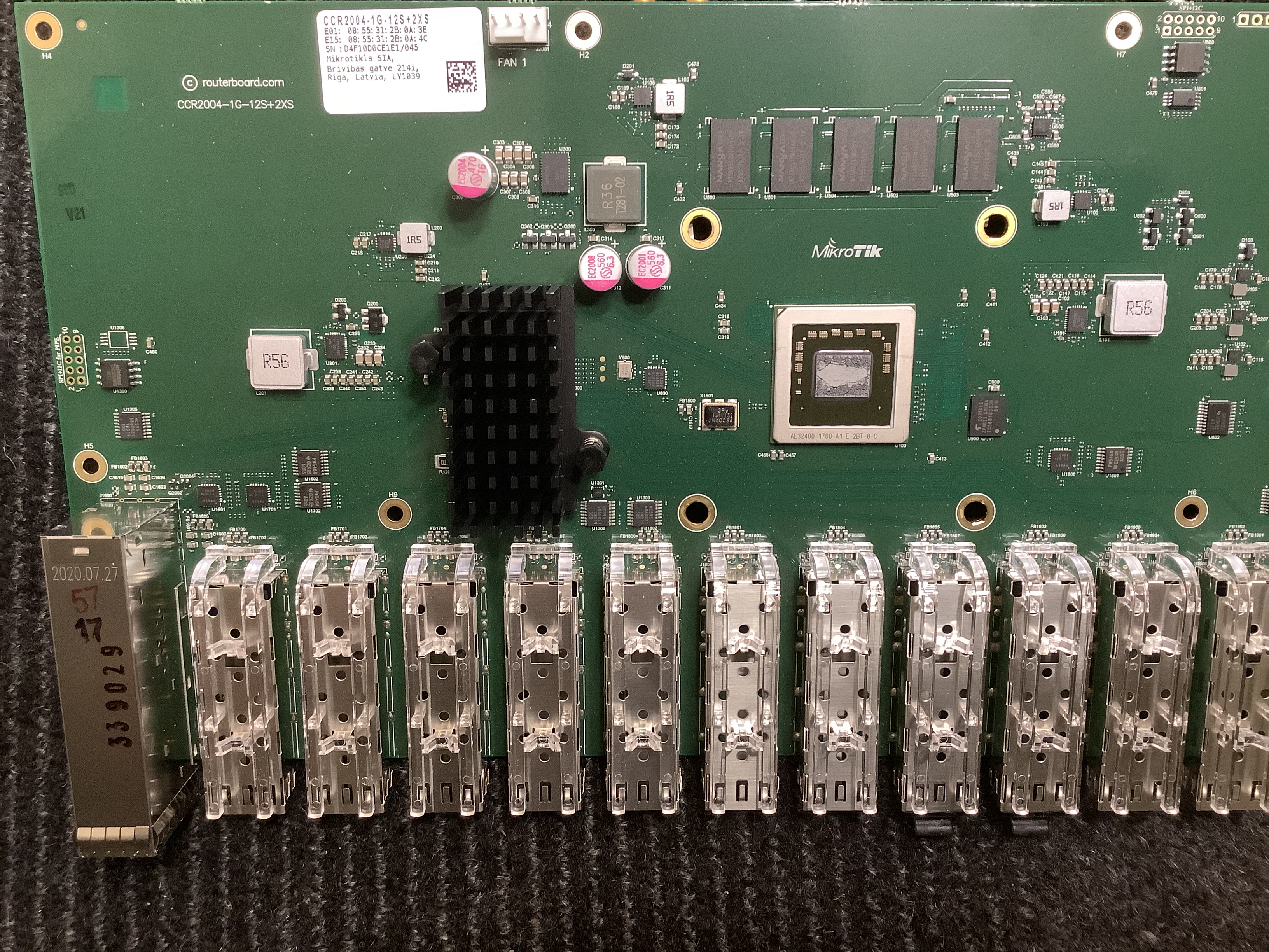
Mods... Sorry that the mods are a bit sloppy. I was in a hurry and these are not final anyway. Its exploratory.

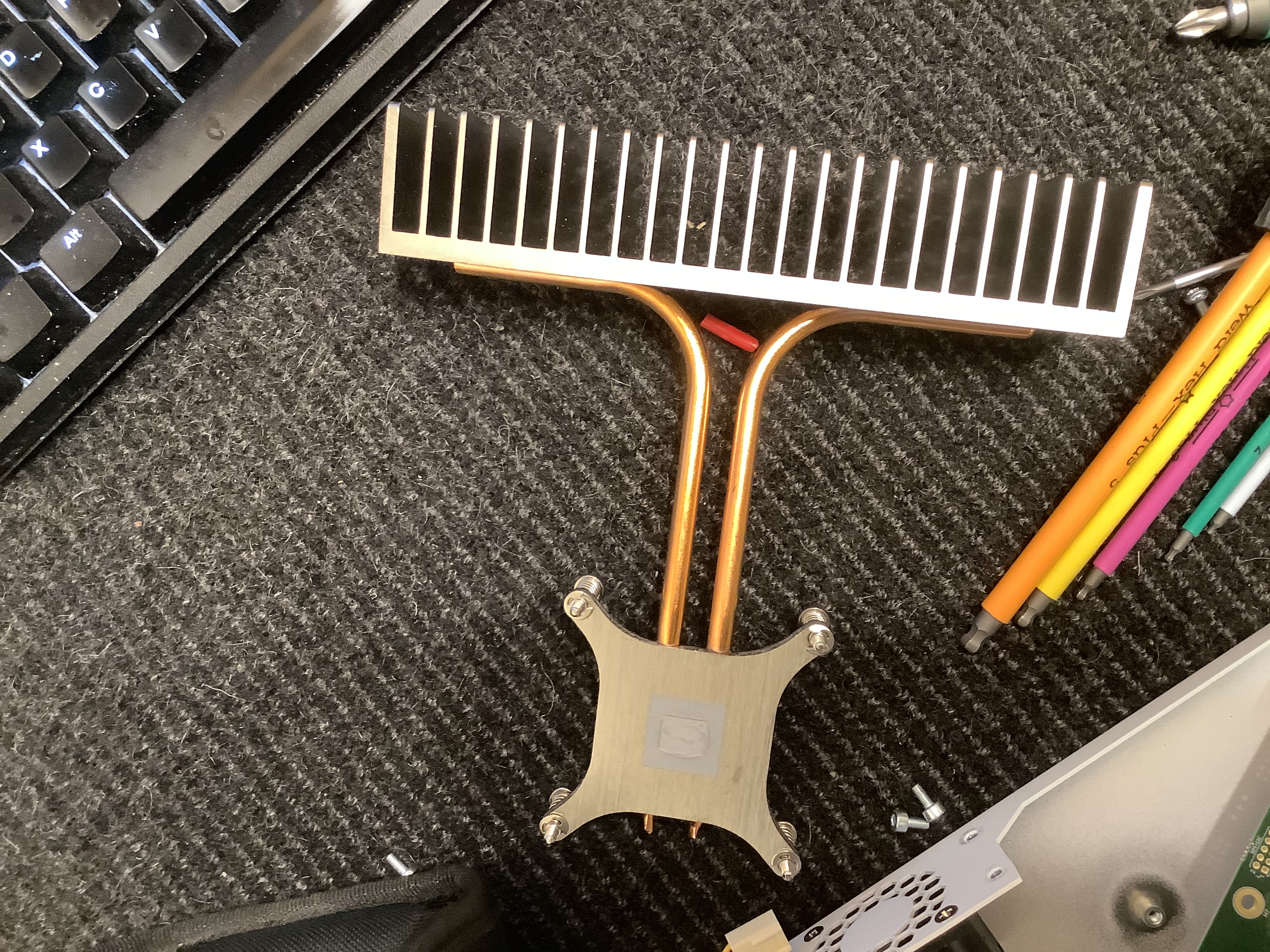
The caps worked out great on the back side. Remember a metal heatsink covers this area and it almost touches the caps. So there is no room back here. The heatsink being misaligned is how it came to me..


Again, don't beat me up for neatness.. Hey it works... hahahahaha...


SO I have been testing it and I will let it go for a bit longer and continue to test...

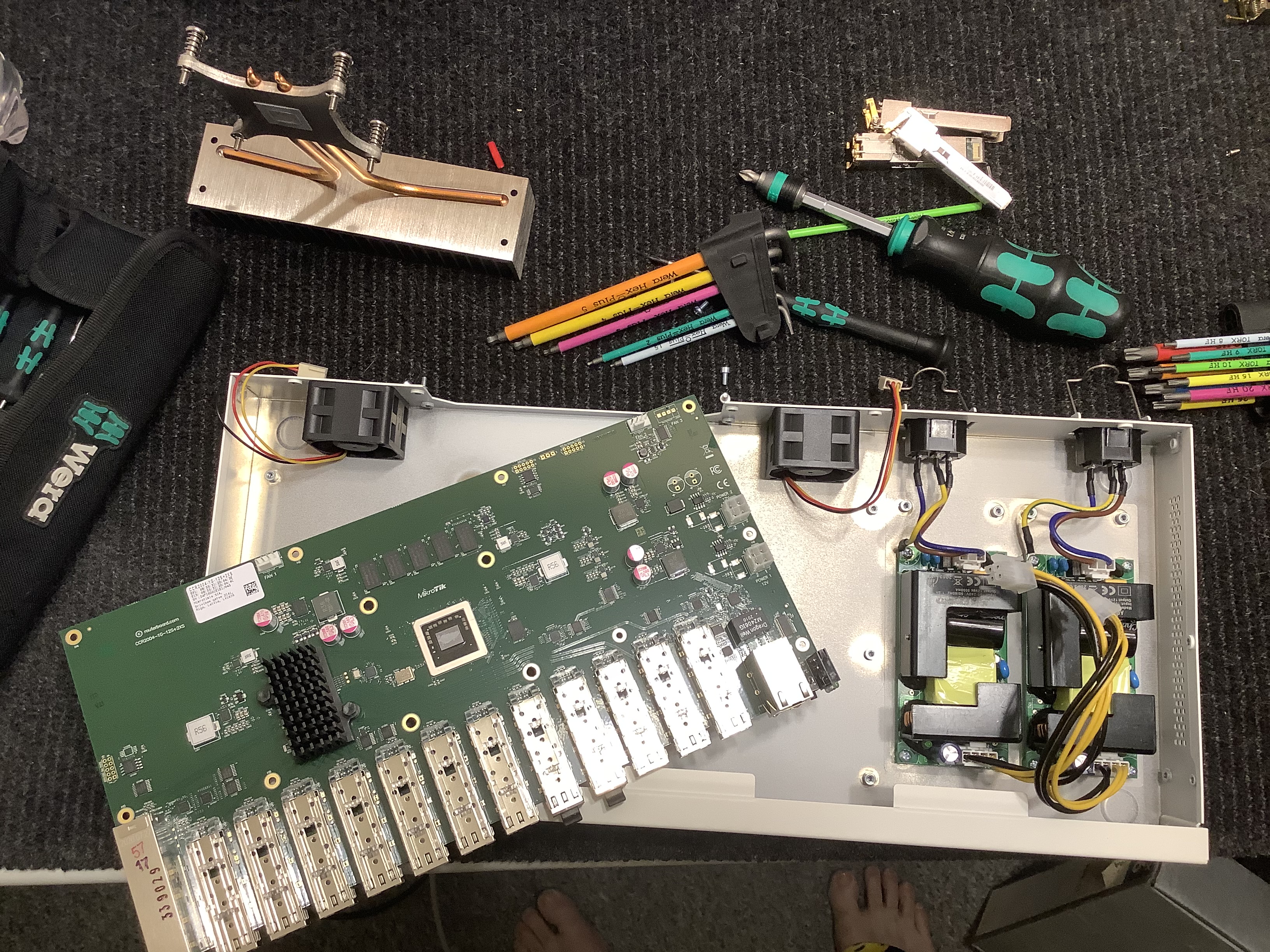
Netx up the router.. I am still pondering what all to do to that.. LOTS OF ROOM....

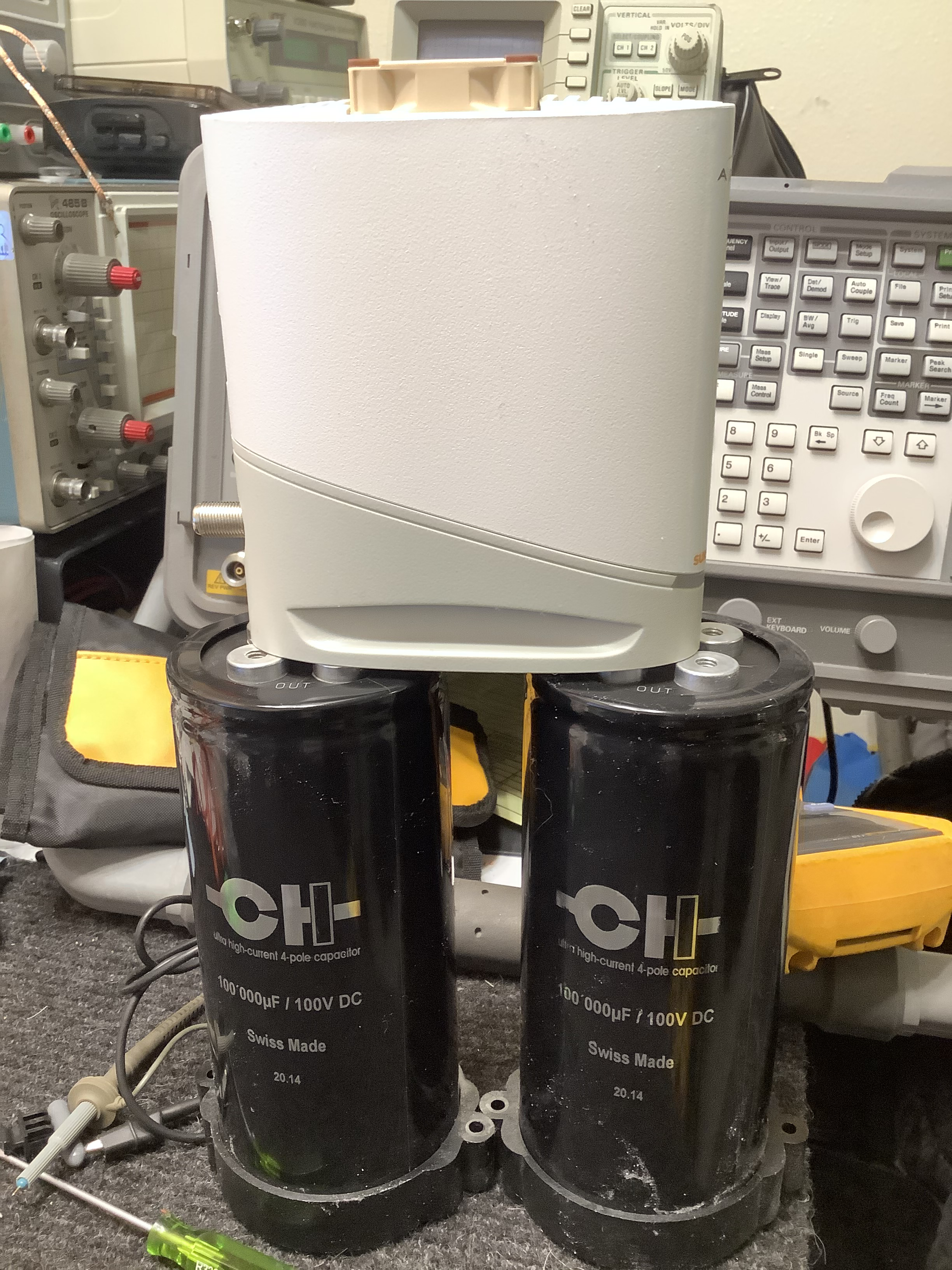
I need some huge audio caps.. Like 16V.. I have 40mm to work with for dia.. I want to build up a bunch of them to like 100,000uF.. What are good caps for this on a switch/router ? WHat is the current fav ? Hopefully something I can get in stock at Mouser or someplace..
 
Last edited:

Xymox

Well-Known Member
Apr 16, 2019
330
279
150
www.appletvx.com
SO modding a modem is time consuming for me.. I go one cap at a time. Then I have to check it, measure things and make sure all is well..

When dropping 10,000 times uF VS what is there, you gotta make sure all is well.. So doing the mods above took 2 full days. Also weird unexpected things could occur, so, I had to have my ISP guy look at it several times before I would go on to the next cap. Its a process. I encountered zero issues, but, I still have to go small steps at a time.

HOWEVER.. Once I get it all done then anyone can then do this without tons of engineering and testing..

My intent with this thread is to hopefully stir up a company to do this work correctly and offer up a modded S33 and a modded Mikrotik router. I want someone to take my ideas and ponderings here and expand on them and make devices.. I just don't have the resources to make products.

So... Take any ideas I put out here and go make things..

One last thing. The modem board would be easy to put into a new case. This would be good to do as it would leave room for good caps and stuff. Also a steel case, or copper, would keep any stray RF from it from getting out to other gear.. I can't do cases. So. Maybe the right person out there could make a special end modem... Not just audio guys would buy it. Gamers spend a LOT of money on stuff like this. Plus normal people might like a better quality modem..
 

Xymox

Well-Known Member
Apr 16, 2019
330
279
150
www.appletvx.com
A-HA... The perfect caps for the modem.. But... Hmmm... Kinda big.... hahahahahahaha...

 
Last edited:
  • Like
Reactions: Mikem53

2ndLiner

Well-Known Member
Dec 16, 2015
297
603
335
In the realm of electronics (and a few other realms, as well) I am not a DIY human but I really enjoy reading about your experiments! I also was struck with a sense of awe & appreciation due to your explanation of how the delivery of information from cable company to end user is accomplished. You have upped my level of gratitude, thank you!
 
  • Like
Reactions: wil

Rob181

Well-Known Member
Oct 1, 2014
207
116
275
In the realm of electronics (and a few other realms, as well) I am not a DIY human but I really enjoy reading about your experiments! I also was struck with a sense of awe & appreciation due to your explanation of how the delivery of information from cable company to end user is accomplished. You have upped my level of gratitude, thank you!

Yep - I completely agree - thank you for the "layman" explanation - I find this fascinating...
 
  • Like
Reactions: 2ndLiner

Mikem53

Well-Known Member
Oct 1, 2020
662
581
105
Awesome write up !! I look forward to your findings based on your experience and Thorough testing!
Appreciate all the time and effort involved to share with us !
 

Kingrex

Well-Known Member
Feb 3, 2019
2,914
2,393
350
Thanks Xymos,
I'm curious. Do Qobuz or Tidal or these other streaming companies to have their systems modded on their end as they transmit.
 

Xymox

Well-Known Member
Apr 16, 2019
330
279
150
www.appletvx.com
Thanks Xymos,
I'm curious. Do Qobuz or Tidal or these other streaming companies to have their systems modded on their end as they transmit.
Wellll....... There is so much **** between them and the ISP, then so much **** in the ISP...... That is kinda my point.. HOWEVER,, if the ethernet physical layer clock on a modem/router/switch is all done well with low phase noise and low jitter, then.. a device like a Regen or SoTM could "reclock" the incoming bytes and clean up the mess.. Within limits..

So a modem/router/switch and things like wires and linears DO matter as they can add jitter to the physical layer clock. Even optical has a clock.

So in my mind.. You gotta clean it all up and then stay clean. Also there might be a benifit to multiple stages of de-jittering and phase noise clean up. These ethernet signals are effected by RF noise, so that is another factor..

SO.. Yea what is IN the Byte coming from Tidal/Qobuz is another story.. And YEA they control that completly. That is not effected tho as it comes to you. Same Byte in/out thru the whole internet to your renderer. Its the jitter and noise you control..

At least that is my thinking ATM..
 

Xymox

Well-Known Member
Apr 16, 2019
330
279
150
www.appletvx.com
Router pondering.....

So I had some caps and started stuffing them into the router. I wont get my Mouser order till late in the week. SO I am biding my time..

I starting looking at the board... While it has mostly traditional voltage regualtors discussed previously, there are 2 that are clearly not the same. They are still switchers, but, they are different in how they operate. I am looking this over. They dont require a big cap on output and do fancy math to keep noise down. However. I dont like that idea. I am a fan of a CAP.. SO I am looking this over to understand this device.

Fancy regulator

I took a look at the clocks.. One that feeds the CPU is a odd number 161.132Mhz. Yea,, thats a odd one.. Not sure what to do about that.. The switch chip tho has a different arrangement.. It uses a clock chip.. Its got a 25Mhz osc that feeds this chip That seems pretty flexible and maybe I can feed that a external 10Mhz clock, but, I gotta reprogram the chip. It does look doable.. Cool ship actually. BUT the chip might be noisy and have a ton of phase noise..

So... I am pondering....

So I am sure that Mikrotik would customize a router if some company wanted them to. They are a small outfit and very flexible. I would bet that could stuff whatever parts someone wanted into any device. OR even make a whole custom board for someone.. So if your a high end audio company, you might wanna talk to Mikrotik about making some cool stuff for you all custom...
 

Xymox

Well-Known Member
Apr 16, 2019
330
279
150
www.appletvx.com
So.... I got Covid, hahaha.. VERY mild symptoms.. This slowed me down a bit BUT has kept me at home quarantined. Bordom brought me around to the router mods.

I spent a bunch of time playing with caps and learning how the router power systems behaved. VERY messy. I hate these pulse width modulated regulators. Someone should do a full set of linear supplies for CPU/Switch chips.

I stuffed a TON of caps into the router. The tantalum caps are critical to knock down the massive spectra of garbage that comes from the PWM regulators. On the supply that feeds the CPU I dropped 3000uF on it by stacking up the low ESR Vishay tant caps. The supplies that feed the SFP+ modules got 2000uF on each. There are 2 supplies, half of the SFP+ modules on each. The switch chip got 2000uF.. And a bunch of supplies got 1000uF. I also put from 330-1000uF on the 12V feeding each supply. Added all up I put 16,000uF of tantalum in.. That is maximum overkill. This was al in addition to the caps already present which i left in place.

I ordered up some basic, very basic, audio caps from Mouser. Handy and fast shipping. I needed massive uF. I stacked these up to 60,000 uF and used some cool wire I had from a previous project that was teflon insulation and solid high purity silver. These are 14 ga. I used 2 in parallel. These were placed in the circuit between where the power lands on the board and its distribution to the regulators. So the 12V rail that feeds all the regulators ended up with 60,000 uF in audio cap + 6,000 uf of tantalum which was spready out in 1000uf caps at each regulator.

Results were good. All noise ( 1 hz - 3Ghz ) was reduced to below 0.25 mv when most started at 50mv. . Short term voltage regulation was generally 0.01%

The system tolerated the the massive increases in power supply caps well not showing any issues.

Ive been testing the system to be sure its all good. When you make huge changes like this you gotta do lots of checking.

Performance wise not much improvement that that I can measure in terms of packet jitter. BUT. The real changes can't be measured that way. I the days ahead I will jump into measuring the actual Ethernet signal. I want to look at the analog aspect of this signal and that is the part I would have had impact on with mods like this..

These are just first general mods. I am still using the switching supply for convenience while I work on it. I will move toward a linear supply and more mods after I do a bunch of testing. I need to let it run and make sure all is well.

I put the caps on the bottom of the board because it made for better connections to the power planes and better for mounting.

IMG_1871.JPG

The audio caps. I will replace these with really good ones and use a LOT more of them. I am thinking like 200,000uF eventually.

IMG_1876.JPG


Also... the RF noise coming from the regulators is really a mess... A video showing this...


Mikem53

Well-Known Member
Oct 1, 2020
662
581
105
Rest and drink plenty of fluids ! Get well.. great vid, cool scope !
 

Xymox

Well-Known Member
Apr 16, 2019
330
279
150
www.appletvx.com
Welll.. I have been exploring Ethernet.. OMG.. Somehow I thought this was some straight forward thing... Nooooooo.... 1000BaseT is just stupid complex. Four-dimensional trellis coded modulation. Five-level pulse amplitude modulation. "The data is transmitted over four copper pairs, eight bits at a time. First, eight bits of data are expanded into four three-bit symbols through a non-trivial scrambling procedure based on a linear feedback shift register. The three-bit symbols are then mapped to voltage levels which vary continuously during transmission.."

"scrambling can help to eliminate such strong high frequency components (by temporally decorrelating the data on the channel.)" "“spatial decorrelation” assists the receiver on the channel from distinguishing the desired signal from the background noise."

"A Viterbi Decoder provides error correction. Not just error detection like most other LAN block codes."

Sooooo.... My brain hurts...

What is going thru a Ethernet cable is HIGHLY complex.

Like I described about cable modems you end up with a constellation of points, lights from my example on modems. BUT unlike OFDM or QAM in cable modems these constellations can vary is shape and size. A tremendous number of things are determined when you first plug in a cable. Plus how the modulation, and all its parameters, end up will vary from system to system and cable to cable depending on this negotiation..

On top of that there are various methods of error correction. No link is free of errors and correction. How much there is adds to jitter.

The very base analog signal of all this is very weird. " Four-dimensional trellis coded modulation.".. It has 5 analog voltage levels. Its not just on/off - 1/0..

This actually explains a lot I think as really there is a D/A and then a A/D going on for each wire pair in the 4 pair cable. How well it does this D/A - A/D really impacts error correction. Noise on the cable could have all manner of effects on a signal like this. How all of it is synced up between pairs also leads to weirdness. Overall jitter on the base clocks for all this will have all manner of effects on things.

In short.. Ethernet is really transporting a very analog signal. Its not just 1/0... As such it is susceptible to a lot of things.

TURNS OUT that optical uses a lot of this same stuff. So optical is also very analog in nature when you get down to the base signal.

OK so its a huge mess.

Measuring this signal in-depth requires crazy level specialized test equipment. Like $119,000 + Options for Ethernet analysis. Regretfully I can't justify that kind of expense for single use. Makes no sense. I have a nice $6k digital Tek scope and it can't really tell me anything of real meaning about these signals. Spectrum analysis is useless... This document shows some base measurements.

SO there is not a lot I can do to really measure and explore these base signals :( ... I have to wonder how many of the audio switch makers have this gear and actually do the work and measure all the parameters when they design the switches.

This is really frustrating for me as I want to minimize "noise" and work on mods and changes that will impact the Ethernet signal. I cannot do that without the right test equipment. All I can do is guess and listen having no idea what is changing..

Disappointing..
 
Last edited:

2ndLiner

Well-Known Member
Dec 16, 2015
297
603
335
I’m sure, @Xymox, that everyone, myself included, following your research shares your disappointment. I wonder if there is anyone who knows someone who might have access such a testing device. Short of that I say let’s start a Go Fund Me page!
 
Last edited:

Xymox

Well-Known Member
Apr 16, 2019
330
279
150
www.appletvx.com
I’m sure, @Xymox, that everyone, myself included, following your research shares your disappointment. I wonder if there is anyone who knows someone who might have access such a testing device. Short of that I say let’s start a Go Fund Me page!
Haha... Well its OK... While it would be great to see these signals directly.... I understand what is going on. ALL the normal principles involved will improve performance. Power supply improvements will lower the noise floor and stabilize D/A and A/D. The 5 voltage levels in the signal would benifit from really good regulation. This analog signal is fairly wideband and so a flat bandwidth is good. Noise like RFI and EMI will degrade the signal. Clock jitter will matter.

SO.. I dont NEED to see the waveform. It would be VERY helpful but not life and death.

I was more interested because I wanted to use the testing and play with various wires and switches and see if I could corrolate sound changes with actual technical measurements. I feel that is what is needed right now is we need to know what to measure technically so we can improve things in a way were we can really know what changes will matter, and what will not.

$130k is just kinda crazy for as little as it would be used long term. Im sure its possible to rent one if it got down to it.

My guess tho is some mfgrs here have this top end Tek scope. Maybe even with the Ethernet options. Im going to check with a few people I know in the industry. SURELY someone who makes DACs at the highest levels would have one ?

yea..... i admit... I have test equipment lust tho... This is showing just exactly what I need on the display. A nice jitter measurement that would show every bit of noise.. VERY sexy device.. I have tool lust...

ezgif-6-4713074badb1.jpg
 
  • Like
Reactions: 2ndLiner

About us

  • What’s Best Forum is THE forum for high end audio, product reviews, advice and sharing experiences on the best of everything else. This is THE place where audiophiles and audio companies discuss vintage, contemporary and new audio products, music servers, music streamers, computer audio, digital-to-analog converters, turntables, phono stages, cartridges, reel-to-reel tape machines, speakers, headphones and tube and solid-state amplification. Founded in 2010 What’s Best Forum invites intelligent and courteous people of all interests and backgrounds to describe and discuss the best of everything. From beginners to life-long hobbyists to industry professionals, we enjoy learning about new things and meeting new people, and participating in spirited debates.

Quick Navigation

User Menu

Steve Williams
Site Founder | Site Owner | Administrator
Ron Resnick
Site Co-Owner | Administrator
Julian (The Fixer)
Website Build | Marketing Managersing