The web response file for passive sub is full range 6th Oct smoothed apology issued! It was webmaster choice!@Musical Bass
If you've really been able to make any sort of progress and innovation here, that's awesome! But you need to stop expecting people to just believe it because you say it, and listen to the feedback you get.
Go back and take proper measurements to prove your claims, then I think both sales and forum discussions will be much easier afterwards.")
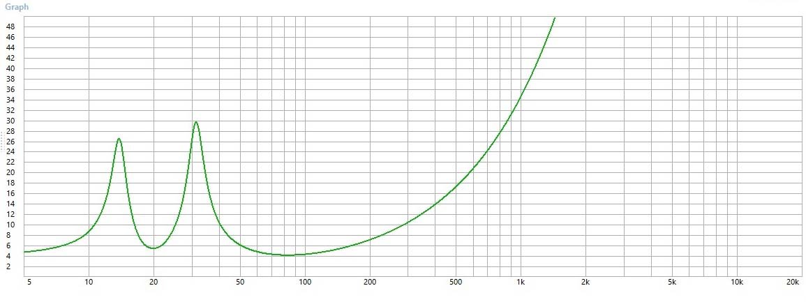
The attached files are associated with the MS-6P to illustrate why we are making our claims. We have a typical impedance graph for a ported subwoofer attached! If someone can present a better example please do. The amplifier only has a direct connection to diaphragm (VC) at the box frequency. If the amplifier doesn’t control the driver it invites modulation from external pressures ( room modes). This will be for most of this conventional systems frequency range.
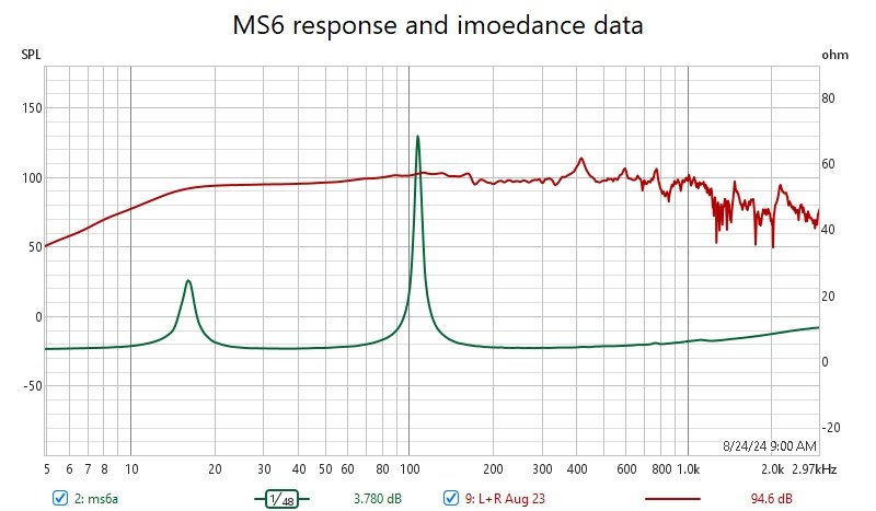
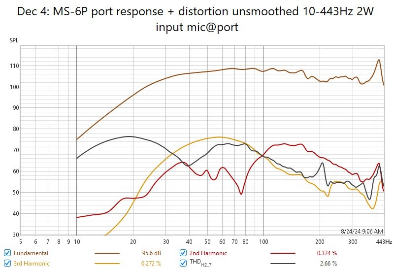
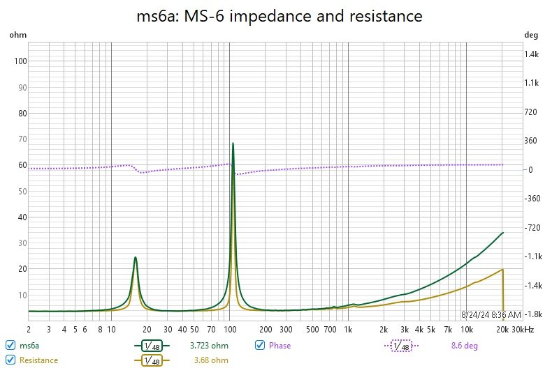
The other graphs are of our MS-6 passive (or active) impedance vs response (not smoothed) and with better resolution. The response and distortion is also plotted both at 2W input with a 32gram moving mass! If you notice the impedance is low over a broad range meaning the amplifier is controlling the driver over the concerned low frequency range making it resistant to external modulation (room modes). The drivers Q is high with little effect on response. The port low frequency response extends below the port peak (no -24db rolloff here) while it outputs energy beyond 200Hz with little error. ! When I use the word grounding it refers to broadband loading of the driver. Minimizing the reactive loading reduces the coupling effects that room modes have on the diaphragm motion.