The story of my Mitsubishi LT-5V turntable.

soundofvoid

WBF Founding Member
Apr 22, 2010
173
11
1,575
Athens/Greece
PART 1
Just been back from vacations and i feel my batteries fully charged!
So i am going to write (in episodes) the story about my resident DIY turntable...
It all started back on 1986 when i finished high school and had successfully
entered the University community.My father bought me as a gift, a Mitsubishi
set of components (amp/preamp/cassette player/tuner and THE Turntable:the LT-5V) plus
floor standing danish Jamo speakers.
Poor man had to give a down payment and i had to help paying up the monthly payments
as the total was 4 times his monthly salary (a schoolteacher).About 1/3 of that was the
cost of the turntable and rightfully so!
IT WAS (AND STILL IS!) EYE CANDY!!!
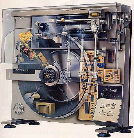
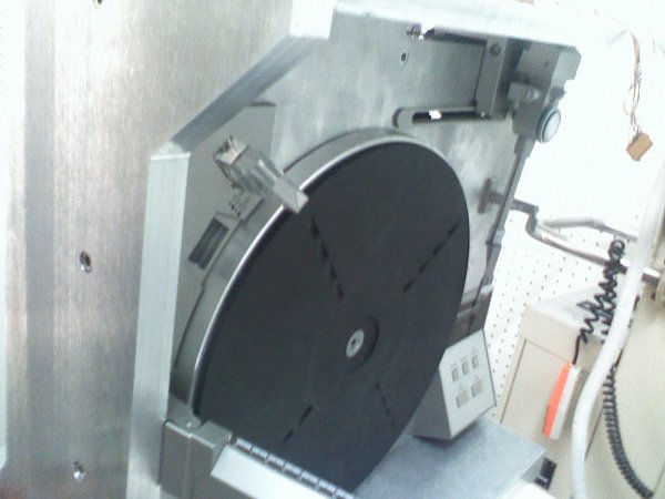
It was vertical,the record had to be pushed onto the platter and stabilized with a clamp,
was completely automatic (record size sensing/speed set/cue in/end lift ) and was using
a complicated parallel tracking arm that in contrary to the norm had a (limited) pivot movement!
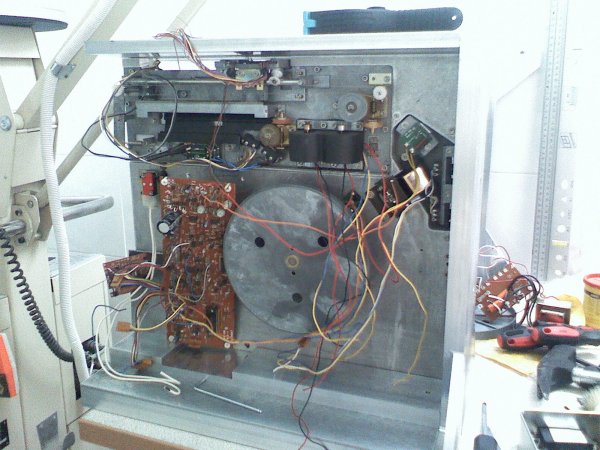
It was belt driven, with a motor that would rotate a sub-platter at the back, connected with
a polished steel rod with the platter on the front.Cartridge was an MM AudioTechnica.
There was not a single person that would come into our house and not gasp in amazement
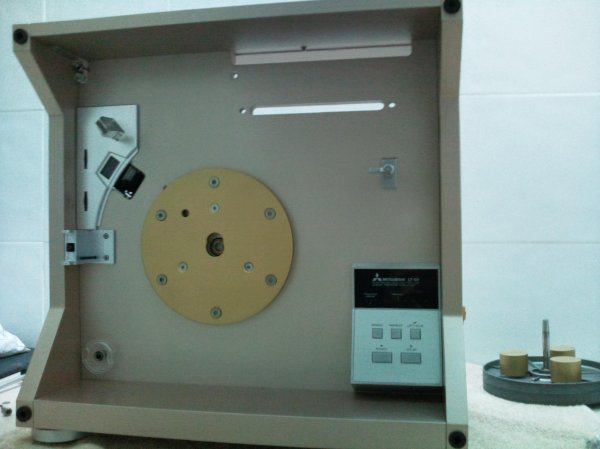
looking at it!See below the "transparent" image that gives an idea of the mechanisms involved!
Through this turntable i listened all the records of my university years...It worked without
a single problem for years and years.
At times other turntables came and went (best was a DENON DP72L) but this was with me
always even after i made my own family and moved to my house.
Through the years i came to understand the way it worked,it's strong points and it's weak ones!
The parallel tracking mech was very well executed but a lot of things could be done to support
it's function.So at first, i took out the power supply and placed it in a separate case,took out the motor,placed it in a separate iron ''tower'' and used a longer belt to rotate the sub-platter.I have designed a different clamp that utilized a stiffer spring to gain better contact between records/platter.
Then i tossed away the original (rather flexible) feet and used in their place a solid 3cm MDF board
with Sony ES feet,used extra MDF boards to strengthen the chassis, changed the tonearm wires
to silver ones and bought a nice VDHul "The Frog" cartridge.Last of all i painted it black from
the original silver.With this transformation the sound moved up several notches and i was in content
for another seven years...
Until an audio friend saw it and said :"I WANT THIS ONE!" and had the money to back up his statement!
I knew that working samples of this were sold at ebay for around 150 euro,and so i promised my
friend that he could have mine the moment i could make a "new" one the way i have dreamed it!
I wanted rigid chassis construction,twin motors,heavier platter/sub-platter assembly,superb power regulation,better tracking and looks to die for.
So i bought two working samples to use as donors for all the parts i needed and started to design
the shape of things to come...
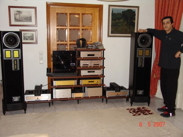
And on the second picture is the LT-5V in my system on the described (modded) shape,
 

Attachments

  • LT-5V..jpg
    LT-5V..jpg
    83.3 KB · Views: 13,754
  • DSC05042..jpg
    DSC05042..jpg
    499 KB · Views: 12,352
Last edited:
  • Like
Reactions: jiho
PART 2
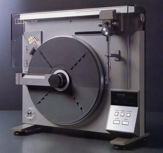
I have to mention that this turntable was sold also under the DIATONE name (a subsidiary of Mitsubishi Heavy Industries).This was mostly for Japan as the Diatone name had a certain audio reputation there, but for the rest of the world it was sold mostly under the Mitsubishi name.Rumors say that in the the electronics, NEC had led a helping hand too.Here is a solid picture of the original thing:Diatone LT-5V..JPG
You can watch it working on youtube:http://www.youtube.com/watch?v=PvuZadkRSPA&p=0CEEB34C579F577E&playnext=1&index=72
If you have to ask why they went into trouble making a vertical standing turntable,the company
brochure blurb was:"The tonearm hangs vertically down, statically balanced in all three dimensions and therefore able to follow even warped discs and cope with vibrations with much less tendency to skip out of the groove."
"The vertical turntable configuration is much less sensitive to feedback than horizontal units because the vibration from the speaker systems is at right angles to the motion of the stylus in the groove"
As for floor/shelf vibrations, i can verify all that.As for warped records it is true for vertically
warped records but it is more sensitive to the off center hole phenomenon!
Indeed, if the center hole of the record is waaay of center the tonearm recognizes it after a few spins
and automatically lifts and returns to the rest position!This is extremely useful for protecting the sensitive cantilever of expensive cartridges!
I have seen a Japanese brochure showing the turntable sans feet screwed to the wall!
And you thought that "on wall" flat screen TVs were a novel idea!
How about "on wall" flat turntables?
If someone asks about the coupling of the record to the platter because the gravity doesn't help due to the platter orientation,i would say that it is a justified question.
Here is a solution that they have used that i discovered after measuring four different platters (and i couldn't believe my eyes!).
The platter is NOT flat!!!It is slightly concave (the periphery is raised with regards to the center) and the pushing action of the center clamp forces the record to "copy"
this form!The difference in height between edge and center is 3mm to all the platters that i have measured,so it is NOT a production mistake but a designers decision!
And to counteract this the headshell is oh so slightly tilted (!) to the center of the record so it always tracks the grooves with the proper azimuth!
This is something that i have never met to any other turntable but it has been done in cd player mechanisms.
All VRDS cd spinners use slightly concave (inverted) "platters" that deform the cd (with the use of a clamp) and the laser head is again slightly tilted to be always perpendicular
to the cd surface...
All this proved to me that serious thought was behind this construction which i could use to build something really special.
I took some hints out of this:http://audio-database.com/MITSUBISHI-DIATONE/player/lt-1-e.htm
This had a more massive construction (about 5 more Kgs) ,direct drive,and even better (the BEST) tracking ability allowing only 0,05 degrees error!
Was only sold in Japan in small numbers and pristine specimens fetch today very high prices...
 
Last edited:
Technics made a series of tables like that...SL-7, SL-10....I think.

John

PS: Your Mitsu looks way better though!
 
No George,it was originally designed to be vertical !
If you place it standing on it's back, like an ordinary table, the tracking tonearm collapses and the platter is facing heavy friction on rotation as it is not designed to rotate this way.
And yes John i think it does,and the good thing is that it has a tonearm to match my needs.Most of the turntables of the era (especially the few attempts on the vertical way) had cheap crappy tonearms.
I once looked up a vertical SHARP turntable having TWIN cartridges mounted each one on each side of the record!You could play both sides without flipping the record!
Very convenient but the record was held in place only from the label part (very unstable) ,the small "tonearms" were a joke, and the whole thing was made of plastic weighing just 5 or so kilos...
At least the LT is a good 12 kgs on original form and more that 25 on my incarnation!
BUT the black one is sold, and this story is about the completely DIY turntable that replaced it!
So keep tuning in to see what happened next...I guarantee that it will be an interesting story!
 
Last edited:
PART-3
First came the #1 sample (very bad condition visually / not working) from a guy in England.Cost:35 pounds plus another 35 for shipping.
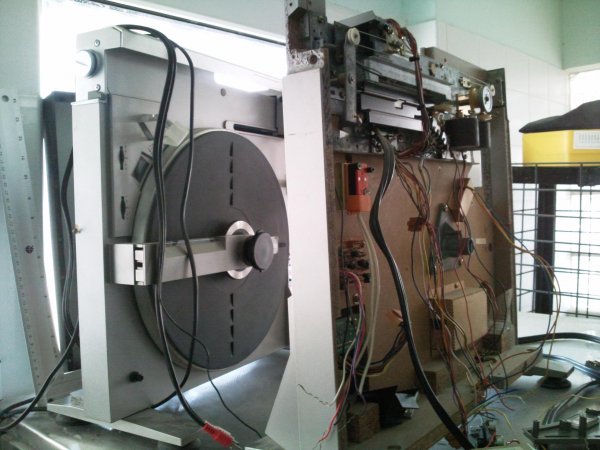
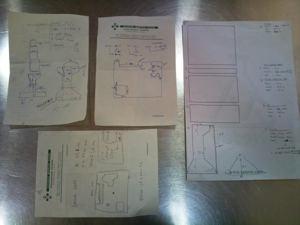
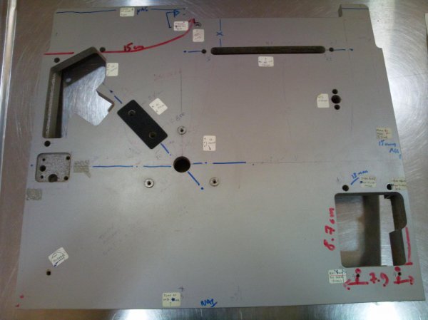
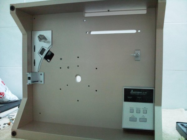
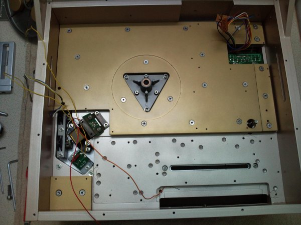
I quickly stripped it down to it's bare MDF chassis to take my measurements.View attachment 688
I was not after an exact copy of the chassis as i wanted it more compact and more rigid.
I had to design it so that everything would be as close as physically and electrically possible.
The only parameter that could not be altered was the distance and position of the rolling
parallel tracking mechanism to the spindle.
I moved the position of the buttons cluster closer to the platter and also moved the position of the
speed control/stroboscope and the clamp/measuring cluster as i decided to use a separate heavy duty clamp.
This enabled me to reduce it's width by 3cms and i also managed to reduced the total height of the turntable by a further 1,5 cms.
I have kept for archiving reasons some early thoughts and drawings from that era.View attachment 689
Then it was off to the CNC shop where after many visits and conversations about materials and CAD
drawings i have decided on using a "soft" type of aluminum for the main part of the chassis
(where all parts are attached) and harder type of aluminum for the other parts.
I ordered both sides machining and drilling for all the main openings/holes but for the countless
screws that would hold various attachments /boards/subsystems i decided to make on my own
when i would have the metal parts in my hands.
I knew it would be a difficult job to do but the CAD files were paid by the hour and my cost would
be sky-high for the myriad of holes to compute and execute!
So i went out and bought a fine tap and die set to be ready for the task.
In the meantime my search through ebay was fruitful enough and made me an owner of
another couple of LT-5Vs, this time much better examples!
The first one was pristine actually as it was stored for more than 20 years by the widow of a
german audiophile.It costed me around 250 euros and about 50 more for shipping.
The second came from Denmark (150+50 euros) ,slightly used ,needed new belts but never the less a fine example!
Photo0202..jpg
Now all i had to do was wait for the first pieces to come out of the CNC machine.
You have to see the look on their faces when they ask you "How many pieces?" and you answer "One!"
Most of the times they think that you must be crazy to go into such an expense and trouble for just one piece!
Of course a certain percentage of insanity is vital when you are after something so complicated and time consuming...
 
Last edited:
And third:Photo0200..jpg
 
Last edited:
Then it was off to the CNC shop

1. What convinced you not to attempt to do the work yourself? You already had the MDF template from the donor table. Why go CNC?

2. How does the sound of this table design differ from conventional tables? You mentioned "tracking on warped records", please expand beyond this single characteristic.
 
Last edited by a moderator:
George,you may have skipped that:
"Then it was off to the CNC shop where after many visits and conversations about materials and CAD
drawings i have decided on using a "soft" type of aluminum for the main part of the chassis
(where all parts are attached) and harder type of aluminum for the other parts.
I ordered both sides machining and drilling for all the main openings/holes but for the countless
screws that would hold various attachments /boards/subsystems i decided to make on my own
when i would have the metal parts in my hands."
I couldn't possibly cut to exact measures the thick aluminum plates that would constitute the new chassis!You need a lathe for that!
I had made my mind on NOT using any "wooden" material on my new baby.This was going to be all metal version!
Regarding the manufacturer stating about the tracking ability of the arm all i can test is that although i have around
a 1000+ LP's ,many of which have been bought second hand and in less than pristine condition,i have not met a single song
that the cartridge skips!You may hear from time to time the odd "THACK" sound but magically the tip finds the right groove!
On using various test LP's the tracking score is consistently very high!
Even when a record has an off center spindle hole and the whole arm is in limbo trying to stay on right angle to the tip,
it doesn't skip at all!It's just when this is TOO much, it lifts and returns to the rest point,just like saying:"give me a break!"
Please have in mind that this arm is a parallel tracking one BUT has -a rather limited (+/- 5 deg)- pivoted movement too!
With the use of leds and light sensors it understands when it's not vertical so that the servo is able to correct the position.
One more thing:My records stay healthy for decades!I don't know where else to attribute this (my cartridges have changed through
the years from A.Technica to Stanton to Grado to VDH MC2 to VDH FROG to VDH CONDOR) but to the quality of the tracking...
Although it is not a light arm (medium to heavy) it has a certain lightness in tracking that i cannot quite describe.
A similar (and absolute fave of mine regarding pivoted arms) is the Dynavector DV 507 which is also a brute of an arm but
tracks lightly like it's on slicks!
 
Last edited:
PART-4
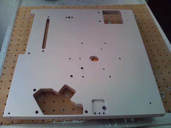
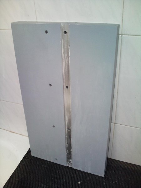
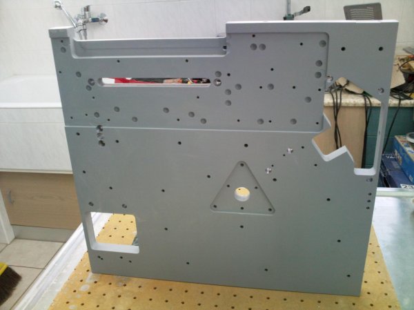
Well, after a certain time and after three different attempts on MDF boards to see how the CAD file was executed by the CNC lathe and subsequent alterations to the original file, we were ready to cut the main piece of the chassis.We had decided on a 2,5 cm thickness (the original board was 2 cms).
As said before this was going to be cut in a softer grade of aluminum that has less "ringing".
The crucial part is the realignment of the flip side of the metal board to the exact calculated position so that the file execution of the back side is carried out in alignment to the front.
Needless to say that i was right above their shoulders watching things closely.
It took the lathe 4 hours to complete the work on both sides.When i took it in my hands i was in heaven.
As we say in my country: "the water had started to run through the channel".
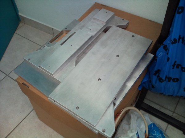
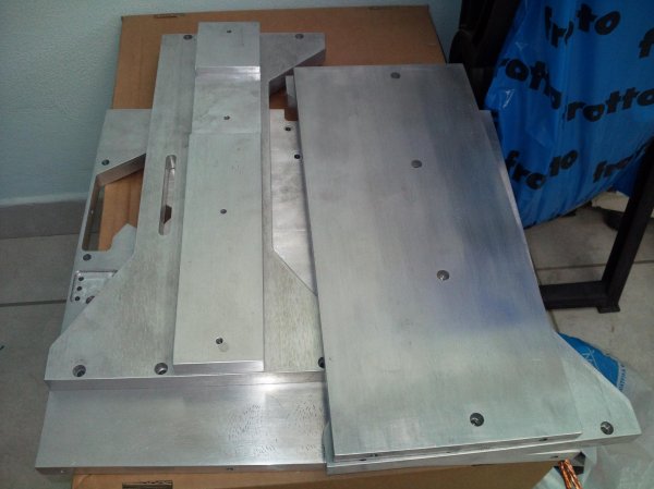
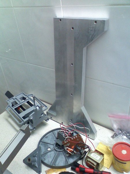
The next day the other parts were cut.These were 4 more:a 3cm thick base plate, two side plates and a smaller bottom plate with 2 cm thickness, and a top plate with 1.5 cm thickness.
These were cut from a very hard/dense aluminum alloy used in aircraft construction.
They were going to be screwed together with M8 inox bolts calculated so that their heads would be flush to the metal surface when tightened.
See the metal boards when cut:View attachment 725View attachment 726
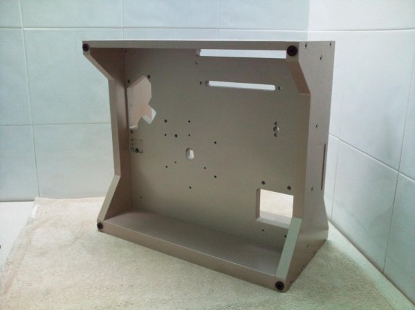
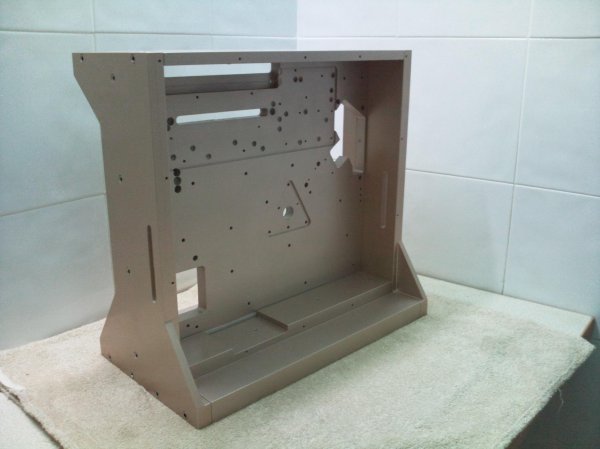
Then i had to screw things together and see if my measurements have been correctly executed.A three hours session on my bench and it started to look like the image in my mind:Photo0031..jpgPhoto0032..jpg121608112036..jpg.
121608112240..jpg121608112016..jpg.
All gelled together nicely and i was very happy with the outcome so far.
The next step was to unscrew everything and prepare myself for the messy work: prep and paint!
 
Last edited:
PART 5
Many of you (that are watching the DIY section) should have come across the difficulties of painting.From my past experience i knew that first i had to get rid of any grit or anomaly of the metal surfaces.
A first sanding with # 400 sanding paper was done.After that a thorough cleaning so all the surfaces were clean from dust and hand oil.
Then i took one piece at a time inside a small ''painting room" with good ventilation that i had prepared the days of CAD planning.Three coats of epoxy primer was sprayed on one side,left to dry for a day
under a UV lamp, and then the same job on the flip side.
Then all pieces were ready for the next sanding session:wet and dry sanding until the plates were satin smooth to the touch of fingers.This is a crucial point:don't expect from the paint to "cover" anything!
When it is painted it will only show worse!Accept nothing less from perfection from the wet and dry sanding stage if you want a professional result!See the outcome:View attachment 739View attachment 740View attachment 741
And now i had reach the point of the color selection...Off to the paint shop and with a sample of a side board from my Sony SCD 777Es at hand,i tried to find the best match to this satin-champagne-gold hue!
It was not easy as this is not a paint but an anodizing process on naked aluminum.Anyway i have found a pretty close approximation and ordered a quantity of purpose made spray cans.
Again the same procedure was followed:spraying three coats on one side,let it dry under UV for a day and then three coats to the other side etc etc.
It came out very nice!Of course the color was not a complete match but i was very happy with the result!Photo0084..jpg
Last stage was the clear coat and there i went for the satin effect (not glass shiny) as i wanted it to look as much closer to the anodized aluminum of my other components.
Another three coats were applied to each side and were let to dry for a week before i attempted
a little hand rubbing with polishing paste to bring it where i wanted it to be.
After that it was time for the assembly...
 
Last edited:
The photos are messing with my nerves-probably due to big files...
After primer:Photo0058..jpgPhoto0083..jpg
 
Last edited:
PART-6
So here i was with all the parts painted and polished,ready to be assembled.I had my supply of inox allen bolts and inox washers ,cleaned up a nice table and used a big bathroom towel to set it on
so that there would be no scratches underneath!
First was the base with the main chassis part.I had left the interlocking channels unpainted so that the paint thickness would not mess with my measurements.Four bolts later they were mated!
Then was time for the smaller base part that also secures from underside bolts to the base and front part.
All nice and clean and then tilt to one side and bolt on the side panel and then to the other side
and bolt on the opposite one.
Then the top had to be added and the skeleton was ready!
I weighted the whole thing and found it to be 38 kilos!Not bad - for starters...
Photo0094..jpgPhoto0096..jpg
Now i had a solid base to build upon...
But further visits to the CNC shop were needed to design and cut the motor housings and the bronze
parts...
 
Last edited:
PART-7
I had to measure the exact height of the spindle so that i could design motor housings that put the motor shaft on the same height.
The plan was to use two motors -one on each side of the turntable so that the belt "pull" of each one would be equalized by the belt "pull"
of the other.
In the height calculation i had to include the final height of the spindle (including spikes and cups etc etc).
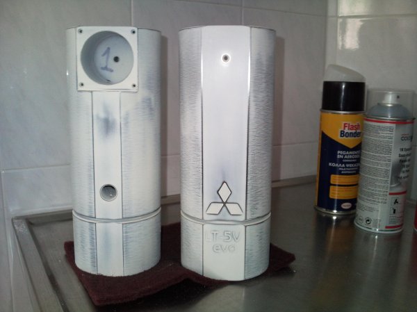
I designed a cylindrical "tower" with two flat surfaces on front and back with all the proper openings for the motor,the wires,the led and the connector.
The material is leaded iron.
Last touch was the engraving of the logo of the Mitsubishi brand plus the "LT-5V evo" sign -that i could not resist!See them when after sanding and primer.Photo0026..jpg
The same material was used in cutting the four spikes that would support the turntable.
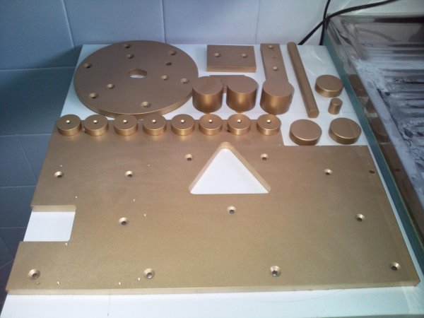
Their cups were cut from bronze as where a number of "reiforcement" plates and other bits and pieces that were going to be used in specific areas to obtain specific results.
See them after final paint:Photo0025..jpg
And now, all these had to be bolted on...
 
The photos are messing with my nerves-probably due to big files...

Then post smaller pictures, I keep resorting to using the Crtl button and the scroll wheel to shrink them down to fit my screen.

The Ctrl button and (-) key at the same time also shrinks it down.

Doing a Ctrl and zero button restores it to original size.
 
Gee!Thanks George!I 've never thought it could be this easy!I will try it with my next part and see what happens...
 
PART-8
I have mentioned the bronze parts but not what was i after incorporating them in my design.
The idea was to dampen vibrations of the aluminum chassis by using another metal that has
different vibration characteristics.I was especially aiming for the area around the spindle carrier.
So two bronze plates were cut.The big one to go on the back side and one smaller (round) under the platter.
Both were 1 cm thick (maximum thickness i could use under the platter) and were bolted to the aluminum chassis with M6 bolts with an intermediate sheet of silicone between the two metal surfaces.
View attachment 799View attachment 800
Together with these i have bolted on the various subsystems (stroboscope/buttons cluster) that i had painted in a silver color (with a bit of flakes thrown in for "sparkle").
All champagne gold would look a bit dull and so i went for the bi-color approach...Photo0103..jpg
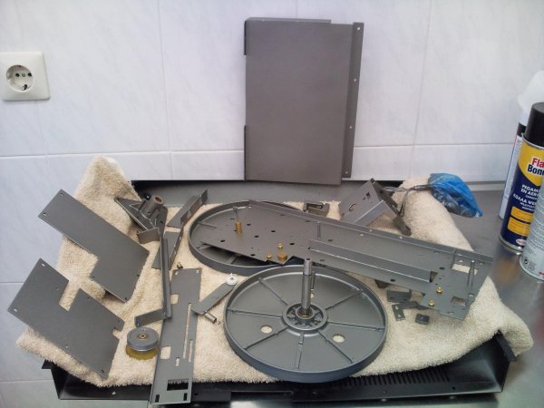
When everything whent to it's place,i had to strip and paint all the tracking mechanism parts
and other sheet metal bits and pieces that would go on the back side of the turntable.Photo0030..jpg
But these had to wait a bit before being attached, for the platter/subplatter/sindle carrier modifications...
 
Problems again...Here are the pictures with the bronze plates attached.Photo0105..jpgPhoto0107..jpg
I have to find a way to compress and store to another file the pictures and drag them from there...
The silicone sheet (1mm) is wonderfull for "bonding" the two metals together!The added
dampening of the two different metals plus silicone makes the whole thing perfectly immune to vibration!
When i had to unscrew the bronze back plate to feed some wires under it, it took a whole day to separate from the aluminum!
Atmo pressure kept the plates bonded together and i had to leave them overnight with just one loose screw to keep it from falling!
 
PART-9
Having weighted the platter (1650 gr) and subplatter (650 gr), and provided that i was going to use two motors,i was ready to make it a bit heavier.
Adding weight on the periphery of a spinning platter is good for increasing the speed accuracy.This is done by increasing the rotational inertia.
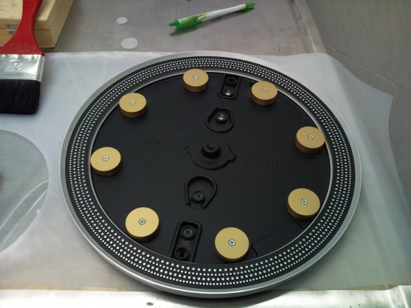
So i had calculated eight bronze weights that would add 850 grams on the platter.They were measured to be of exact the same weight and placed
(screw and glue) under the platter.This gave me a platter weighing 2,5 kilos.
Photo0052..jpg
On this weight i had to add the weight of my new spring loaded solid aluminum clamp (350gr)
plus the weight of a record (opted for 150 gr).This makes the front portion weight a round 3 kilos.
I don't know why Mitsubishi decided on a much lighter subplatter (motor torque reasons?)
but to me this was WRONG and i have found a way to have a 3 kilo subbplatter.
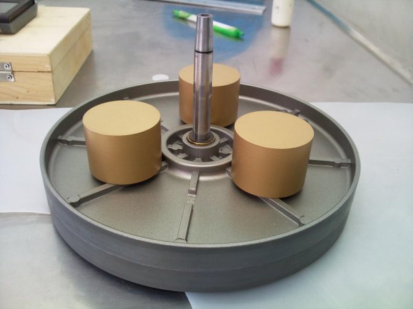
I added two subplatters together (one silicone sheet between them for dampening reasons) which they would hold together by three (two-parted,screwed together) bronze weights.
The whole thing was calculated to weigh (sans spindle) 3 kilos exactly and by this the whole
system balanced with a rotating weight of 6 kilos!
Photo0047..jpg
The spindle carrier is from diecast aluminum,has a 6 cm length,and the spindle is supported on both ends by bronze self lubricating bushings.I pushed one of the bushings exactly in the middle of the carrier (plastic insert and gently tapping it) and added another one on it's first place.
This way i had three bushings (front / center / back) to support the increased weight/friction of the much heavier platter/subplatter combo.A special lubricant was added to reduce friction even further...
When everything was in place,the platter/subplatter assembly was rotating with a lot of friction.
I was expecting that because of the new center bushing that needed to grind in the spindle...
I knew it would take some "burning in" period for it to set nicely and so i started thinking about
the other big matter:the electronics!
 

About us

  • What’s Best Forum is THE forum for high end audio, product reviews, advice and sharing experiences on the best of everything else. This is THE place where audiophiles and audio companies discuss vintage, contemporary and new audio products, music servers, music streamers, computer audio, digital-to-analog converters, turntables, phono stages, cartridges, reel-to-reel tape machines, speakers, headphones and tube and solid-state amplification. Founded in 2010 What’s Best Forum invites intelligent and courteous people of all interests and backgrounds to describe and discuss the best of everything. From beginners to life-long hobbyists to industry professionals, we enjoy learning about new things and meeting new people, and participating in spirited debates.

Quick Navigation

User Menu